wait a minute, that's awesome. I didn't even know you could do that

@pestoman
Your output dc offset will go up a bit, but not enough to cause harm. The question is, will you like the sound of direct vs cap coupled? Only you can answer that. Personally, I am not a fan of the WIMA cap in this position (but do use it plentifully in other circuits!).
I experimented a bit with the Aleph J in my NPXP build - do a search on the Pass Labs forum. For more fun, use a differential source (preamp or dac) and take advantage of the differential input pair in this circuit. That’s how I plan to run my Aleph 60 build .
.
Best,
Anand.
Your output dc offset will go up a bit, but not enough to cause harm. The question is, will you like the sound of direct vs cap coupled? Only you can answer that. Personally, I am not a fan of the WIMA cap in this position (but do use it plentifully in other circuits!).
I experimented a bit with the Aleph J in my NPXP build - do a search on the Pass Labs forum. For more fun, use a differential source (preamp or dac) and take advantage of the differential input pair in this circuit. That’s how I plan to run my Aleph 60 build
.Best,
Anand.
https://www.diyaudio.com/community/threads/aleph-j-illustrated-build-guide.241729/post-7418345
I've corrected the right channel ground lift but have yet to relocated the speaker ground to the Extreme Boky's preferred location at the jumpers near the D+ / D- on the Universal Power Supply.
At that point there was a slight buzz on the left channel interestingly when the preamp is muted. Listenable, not awful, but it prompted me to take the next iterative step of modifying the left channel to see if that helped. It did.
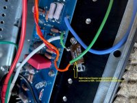
To summarize the change, having read threads on ground lifts here on other FW designs, I lifted the leg of the R2 resistor at it's ground side, which is effectively mimicking cutting the ground trace between GND and GND3 on the PCB. Then run the input ground jumper and a jumper to the ground leg of R2 to an outboard 10R resistor, then a jumper from the other side of that 10R to GND3.
https://www.diyaudio.com/community/threads/aleph-j-illustrated-build-guide.241729/post-6063355
@Zen Mod 's post here convinced me to wait on relocating the negative speaker grounds. If and when I fully disassemble the amp can try @Extreme_Boky relocation of those. For now the amp sounds great with respect to buzz, and in general.
This is how the left channel ground lift now appears:

I've corrected the right channel ground lift but have yet to relocated the speaker ground to the Extreme Boky's preferred location at the jumpers near the D+ / D- on the Universal Power Supply.
At that point there was a slight buzz on the left channel interestingly when the preamp is muted. Listenable, not awful, but it prompted me to take the next iterative step of modifying the left channel to see if that helped. It did.
To summarize the change, having read threads on ground lifts here on other FW designs, I lifted the leg of the R2 resistor at it's ground side, which is effectively mimicking cutting the ground trace between GND and GND3 on the PCB. Then run the input ground jumper and a jumper to the ground leg of R2 to an outboard 10R resistor, then a jumper from the other side of that 10R to GND3.
https://www.diyaudio.com/community/threads/aleph-j-illustrated-build-guide.241729/post-6063355
@Zen Mod 's post here convinced me to wait on relocating the negative speaker grounds. If and when I fully disassemble the amp can try @Extreme_Boky relocation of those. For now the amp sounds great with respect to buzz, and in general.
This is how the left channel ground lift now appears:
@Ben Mah keen observation as always. Note that last photo you reference is from before my correction earlier in the week. Here's the corrected right channel HBR. It matches the left side. Today I've swapped pre-amps to KorgB1. And speakers to Betsy OBs. Sounds good. With an ear directly to each full range driver and volume all the way down, there is the slightest motorboat hash sound detectable. Not enough to cause any immediate need for improvement.

Bit the bullet
Just ordered a 5U aluminum chassis from modushop. I think they're on holiday until 8-21 or 21-8.
Also ordered the transistor kit, boards and and the chassis hardware kit from the store.
Being a lifelong tube guy this should be a nice change of pace, May be leaning on some of the
very knowledgeable folks here for guidance.🙂
The Aleph J is going to be a wonderful amp. The 5U is plenty large enough to support decent bias currents.
Probably the best guidance you will find is at the very beginning of this thread. Study the first couple pages thoroughly before beginning your assembly.
Probably the best guidance you will find is at the very beginning of this thread. Study the first couple pages thoroughly before beginning your assembly.
Congratulations!Bit the bullet
Definitely! Read it all.Probably the best guidance you will find is at the very beginning of this thread. Study the first couple pages thoroughly before beginning your assembly.
And... for newer builders, I can also recommend this blog.
https://diyalephj.blogspot.com/
^last two above know what time it is. Like you I did tube amps ages ago, guitar then lately hifi (EL84 SEP) from scratch. Your early conclusions are on point.Bit the bullet
Just ordered a 5U aluminum chassis from modushop. I think they're on holiday until 8-21 or 21-8.
Also ordered the transistor kit, boards and and the chassis hardware kit from the store.
Being a lifelong tube guy this should be a nice change of pace, May be leaning on some of the
very knowledgeable folks here for guidance.🙂
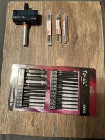
Here's a tidbit - the Garant 'torque thingy' here was a great addition in order to get the MOSFETs mounted correctly. $16. You'll need a 2.5mm driver bit.
https://www.diyaudio.com/community/threads/aleph-j-illustrated-build-guide.241729/post-7388262
Pass:
that would be 0.9Nm
close enough, if tap is proper and long enough in Al material
I recommend a nice wide washer on top.
The TO247 case has good support at the hole, and you
just want to avoid cranking down too hard. We use
torque wrenches set at 8 inch-pounds.
that would be 0.9Nm
close enough, if tap is proper and long enough in Al material
I wouldn't go higher than 1.0N.m as the IRFP240 datasheet shows a mounting torque limit of 1.1 N.m

I set my torque screw driver to 6 lb-In when mounting a TO-247 case using Keratherm insulators. It’s more than sufficient and doesn’t deform the insulation pad as much.
Edit:
Honestly, I didn’t even get the torque screwdriver out last time I mounted transistors. Just good and snug is enough.
Edit:
Honestly, I didn’t even get the torque screwdriver out last time I mounted transistors. Just good and snug is enough.
Last edited:
Before I bought the 1.0 nM I searched the site here extensively. The next wrench value down was 0.9nMm and it seemed the target value was 0.95nM
So I went up 0,05nM to 1.0 as my selection.
Seems good!
So I went up 0,05nM to 1.0 as my selection.
Seems good!
Torque limiting tools for the win. Thats always timeless and solid advice.
But if you have decades of solid experience of never ever over- or under-torqueing anything; and is the owner of a skilled and nimble hand or two: and a head full of common sense:
1. Simply: Use a very thin tool = almost no torque leverage for enhanced ”feel”.
2. When the spring steel split washer is compressed and solidly seated between the bolt and larger washer on the active device, and the Keratherm just barely visibly starts to squeeze: Then you are Optimal and solid on the absolute Peak of the hill.
If you ask me.
🙂🤚
@JeyDee great advice as an old timer car person concur with the feel + observation method.
One note: on my J I used Belleville washers vs. split above the large stainless flat washers. Belleville's don't offer the same obvious visual indicator inherent with split washers, motivating the torque tool buy. Nice feature too is it's handle design allowing you to easily spin on the fastener which is less easy with a tiny Allen wrench.
One note: on my J I used Belleville washers vs. split above the large stainless flat washers. Belleville's don't offer the same obvious visual indicator inherent with split washers, motivating the torque tool buy. Nice feature too is it's handle design allowing you to easily spin on the fastener which is less easy with a tiny Allen wrench.
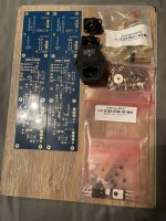
I received shipping confirmation on my 5U pre-drilled chassis today. Shouldn’t take long to get by FedEx. Here’s my collection of stuff so far. I need to see what I have in my shop before making a mouser order. I’ve decided to go dual mono with two donuts. The torque driver folks have some nice German made bottoming taps. I got a 3,4 and 5 MM.^last two above know what time it is. Like you I did tube amps ages ago, guitar then lately hifi (EL84 SEP) from scratch. Your early conclusions are on point.
Here's a tidbit - the Garant 'torque thingy' here was a great addition in order to get the MOSFETs mounted correctly. $16. You'll need a 2.5mm driver bit.
https://www.diyaudio.com/community/threads/aleph-j-illustrated-build-guide.241729/post-7388262
View attachment 1203682
Attachments
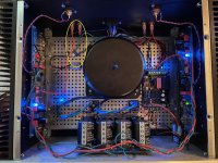
I did it myself... with the invaluable help of this thread and the blogspot thingy. Fun project. Sounds fantastic. Thanks to all!
Attachments

Looks like the left channel speaker ground back panel connector is connected to chassis/safety ground. It should be connected to audio ground, preferably on the amplifier board, and twisted together with the speaker+ wire. I can't tell what is happening with the right channel speaker ground wire.
Attachments
- Home
- Amplifiers
- Pass Labs
- Aleph J illustrated build guide