I read in another thread that R5 disipates about 380mW and should be 0.5W minimum.
Store boards use leads space for 0.5W resistors.
They are 0.25W in BOM Revision D thought..
One is downgraded 0.5W military RN60 and another is regular 0.25W CMF55.
Is R5 1W realy neccesity?
Store boards use leads space for 0.5W resistors.
They are 0.25W in BOM Revision D thought..
One is downgraded 0.5W military RN60 and another is regular 0.25W CMF55.
Is R5 1W realy neccesity?
Thank you, ZenMod!
Somehow I like that idea more than expand resistor to RN65 size.
Still look nice.
Somehow I like that idea more than expand resistor to RN65 size.
Still look nice.
Attachments
Last edited:
OTL bias procedure
On the board there is a pot for OTL Bias. What is the procedure for doing this bias? I've searched here but cannot find anything here that is definitive. If this has been discussed, please send a link or how to find it.
Frankly, I'm not sure what this is. I've been in the tube world for 30+ years and am not familiar with OTL Bias. OTL in a tube amps means they don't have output transformers. I'm guessing it isn't the same in solid state.
Are you using the boards from the store? If so, what schematic are you using? If you're using the store boards, my recommendation would be to follow the build guide posted by 6L6 and replace that pot with the recommended fixed value resistor.
It's a board from the store and I don't believe there is any mention of R8 in the build guide. Once I'm confident I have everything dialed in, I'll replace pots with resistors. Before doing that I want to make sure the OTL bias is correct. Maybe it doesn't matter but I want to be sure.
Greenthumb - use a 1k resistor instead of a pot at R8, or just set the 2k pot at the mid-point and forget about it.
I think Dr. Greenthumb was referring to the LTP bias. Not sure where “OTL” came from.
As 6L6 advised, a 1kohm resistor in R8 works.
As 6L6 advised, a 1kohm resistor in R8 works.
I think Dr. Greenthumb was referring to the LTP bias. Not sure where “OTL” came from.
As 6L6 advised, a 1kohm resistor in R8 works.
You're correct, LTP. I was looking at OTL tube amps that day.
certainly

I can't resist..
Zen Mod, can you please help.
What does it need to change Zener to series LED's in Aleph scheme?
Is it as simple as change Zener diode with series LED's but in opposite direction?
Should I change any other scheme parts and their values?
I drew this cheme with only Zener changed.
Plan was 4 LEDs in series with about 2.25Vf
Maybe Kingbright WP3A10HD (Red) or WP710A10PGD (Green).
Attachments
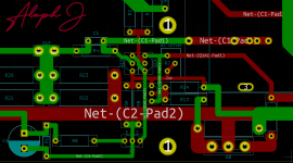
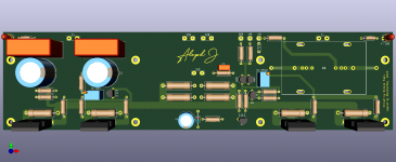
Yes I try to make my own UMS heatsink compatile board in KiCad.
My first try in Cad software and my first board.
My first try in Cad software and my first board.
sleepy now, will sketch tomorrow for you
single BC up is overburden (think heat)
for CCS - use ring of two, then you don't need LEDs
see my Babelfishes
BC+ BD
single BC up is overburden (think heat)
for CCS - use ring of two, then you don't need LEDs
see my Babelfishes
BC+ BD
But can LED's stay?.. 🙂
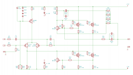
This is DIY Audio store Aleph J scheme with changes to R5 split in two and changed Zener to a string of LED's.
I only have doubts change Zener diode is as simple as that.
This is DIY Audio store Aleph J scheme with changes to R5 split in two and changed Zener to a string of LED's.
I only have doubts change Zener diode is as simple as that.
- Home
- Amplifiers
- Pass Labs
- Aleph J for Universal Mounting Spec