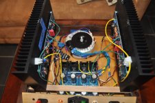
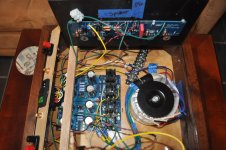
We need a tighter shot, but just looking at the picture on the right that includes the full PSU with the output wiring, I cannot clearly see that you have BOTH V+ and V- running to each board along with GND. You're using the same coloring of wires, so it gets a bit jumbled. I don't think I see enough connections to your euroblocks.
Confirm that you have it wired precisely like below or correct it to be exactly like below.
The side of the PSU closest to the heatsink in the picture on the right. That should be the V- side of the board. Take:
One wire from V- on PSU board to left channel amp board V-
One wire from V- on PSU board to right channel amp board V-
One wire from GND on PSU to left channel amp board GND - hook it back up. It looks cut.
One wire from GND on PSU to right channel amp board GND.
Then on the other side of the PSU board, that is your V+ side. Take:
One wire from V+ on PSU board to left channel amp board V+
One wire from V+ on PSU board to right channel amp board V+
It is NOT one side of the PSU to power one channel, and one side to power the other channel. Which, I think is what I see, but I just can't be sure with your picture and the jumbles of wire.
Edited to add - Before doing above, CONFIRM that the PSU sides match my description by using your DMM to measure the rails per previous instructions and/or read the tiny print with V--- and V+++ next to the Euroblocks.
Edited to fix a copy paste error on V+ side. Sorry. V+ obviously goes to V+. 🙂
Last edited:
It's done. That's how I had it wired, one side for one channel, visa versa.
Should I run a PS ground to star ground?
I'll conduct another offset/bias test.
Should I run a PS ground to star ground?
I'll conduct another offset/bias test.
Glad you have it revised.
Reset pots to center points.
Dim Bulb test with new wiring.
re: star ground. PSU Ground to chassis ground. You'll put a thermistor in the middle later.
If passes dim bulb. Remove and carry on with bias / offset.
Nice job.
Reset pots to center points.
Dim Bulb test with new wiring.
re: star ground. PSU Ground to chassis ground. You'll put a thermistor in the middle later.
If passes dim bulb. Remove and carry on with bias / offset.
Nice job.

Another complete wiring check. Bias/offset set both sides. Still, sound from one side. I'm figuring what's left is phono wiring. I'll probably get to that next but I can't imagine that's the issue. Maybe I should connect the RCA's grounds together.
If bias and offset are OK on both sides then the quiet side is likely an input/output wiring issue.
I hope so. I'll get on it again tomorrow. I'm having a Whiskey with my egg nog.
If I can set offset wouldn't this tell me that wiring portion is ok?
If I can set offset wouldn't this tell me that wiring portion is ok?
Sorry for the mess in the box. I've taken this apart 30 times in the last 30 hours. Cleanup will commence when I have stereo sound.
If I can set offset wouldn't this tell me that wiring portion is ok?
It means the amp is working properly in DC. Music is AC.
More investigation is required, but having DC responding properly is very, very good news.
I found something a bit odd. I have continuity when I touch ground to pos side of output on unresponsive side.
Issue fixed ( fingers crossed ) I re-wired output on unresponsive side. Offsest & bias set. Unit is cooking as I type.
No pics at this moment in time. Looks like a birds nest in there.
Thermistors arrived BTW.
No pics at this moment in time. Looks like a birds nest in there.
Thermistors arrived BTW.
 I have chores to do outside.
Audio making it from input to output?
If I understand this statement yes. I'm elated.
- Home
- Amplifiers
- Pass Labs
- Aleph J build guide for noobs