🙂 Leave your terminal strip alone until you get your thermistors.
Amp board:
Did you fix the input jumpers?
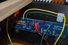
I don't see anything to electrically isolate your MOSFETs from your heatsinks. It could be there. I just can't see it. What did you use?
Only one board wired to the PSU? It's advised to test one at a time.
Per 6L6 earlier - don't move the pots if you haven't already.
Read 6L6's first couple posts in his build guide re: set up and bias. Follow that. I recommend not doing anything further until you feel like you understand it. If not, I'd wait for the guide the OP is completing.
Aleph J illustrated build guide
Amp board:
Did you fix the input jumpers?
I don't see anything to electrically isolate your MOSFETs from your heatsinks. It could be there. I just can't see it. What did you use?
Only one board wired to the PSU? It's advised to test one at a time.
Per 6L6 earlier - don't move the pots if you haven't already.
Read 6L6's first couple posts in his build guide re: set up and bias. Follow that. I recommend not doing anything further until you feel like you understand it. If not, I'd wait for the guide the OP is completing.
Aleph J illustrated build guide
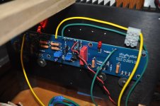
I use this vinyl looking stuff to isolate the mosfets I bought from Mouser.
Jumpers fixed
I'll read 6L6 posts about bias and thank's
Jumpers fixed
I'll read 6L6 posts about bias and thank's
It's going well. Doing a warm up left side and I'll readjust offset & bias the move on to the right side.
We should be making music in an hour.
I have an important question about putting power to my mega labor of love speakers.
Should I use a test pair instead?
We should be making music in an hour.
I have an important question about putting power to my mega labor of love speakers.
Should I use a test pair instead?
Fantastic news!
I always use a test pair for a day or two and check for wandering bias and offset. I defer to others for any other helpful tips.
I always use a test pair for a day or two and check for wandering bias and offset. I defer to others for any other helpful tips.
Right side warm up now.
Heatsinks are just warm to the touch. Same with PS heatsinks.
Heatsinks are just warm to the touch. Same with PS heatsinks.
Last edited:
Theres something about my passive volume control this amp doesn't like. When I hook it up to the inputs one pair of LED on the amp circuit go out. No sound. Even when I plug the speakers in those same LED's dim.
Last edited:
^ 
6L6 - I've never used the LTP bias pot. I use fixed 1kR. Is 500R (If I'm reading if correctly) pot ok there? Assuming factory set at 250R? I thought 2k needed to be there set to mid point, but lower may be okay. Out of my depth on that.
Edited to add - If I were in your place, after adding the GND from each amp board to the PSU, I would reset all my pots to mid-point before applying power again. Someone else should confirm if that's necessary / advised. Then I would rebias / renull offset.
Each amp board needs V+ and V-. Connections in upper left and upper right of the boards in your picture. Three wires for each board to PSU. V+, V-, and GND.
6L6 - I've never used the LTP bias pot. I use fixed 1kR. Is 500R (If I'm reading if correctly) pot ok there? Assuming factory set at 250R? I thought 2k needed to be there set to mid point, but lower may be okay. Out of my depth on that.
Edited to add - If I were in your place, after adding the GND from each amp board to the PSU, I would reset all my pots to mid-point before applying power again. Someone else should confirm if that's necessary / advised. Then I would rebias / renull offset.
Last edited:
If 1K is the nominal value, you want that value in the middle of the potentiometer’s range, so 2K would be required — it can select 0ohm to 2000ohm.
A 500ohm pot can select 0ohm to 500ohm
In that position, a 1K resistor is best.
A 500ohm pot can select 0ohm to 500ohm
In that position, a 1K resistor is best.
If you have a pot at the R7 position for DC offset adjustment, there really isn't
a need for R8 to be adjustable and going with a fixed 1K resistor there gives you
a nice known bias current value for the LTP. (Of course, silly me didn't do that
in my build, but since my AJ is working fine, I'm not going to open it up just for
that.)
a need for R8 to be adjustable and going with a fixed 1K resistor there gives you
a nice known bias current value for the LTP. (Of course, silly me didn't do that
in my build, but since my AJ is working fine, I'm not going to open it up just for
that.)
Is PSU ground attached to the amp PCBs?
The only grounds I have going to the psb are speaker & input as far as I can tell
I suppose it doesn't matter which ground I attach the PS ground to, G1, G2,G3. I'll reset pos and start over. Just woke up and need a cup of coffee first.
Nope. Any of them will do.
After coffee, confirm understanding above re: your plans for the LTP bias pot. I can tell you that fixed 1k resistors are common instead of a 2k pot, but both would work.
What I can't tell you is if a max of 500R at that location is enough or if only having 250R (assuming pot at midpoint) at startup may cause issues. That's out of my depth. Dennis and 6L6 confirmed the preferred values from my previous post. Thanks guys! What has yet to be confirmed is if it will function properly the way you have it.
Just check also to see if I read that pot value correctly. My vision is not great, but I think I saw "501" => 500R
Others could chime in to confirm if it will work or if you need to change it before attempting to bias / null offset again. That's out of my depth re: circuit knowledge.
Good eyes! I went back and found post #545:
https://www.diyaudio.com/forums/pass-labs/357002-aleph-build-guide-noobs-55.html#post6440724
It looks like a 500R pot at the LTP bias position.
This would not be good. If you set it at mid point (250R) you get 4x the current
through your jfets compared to 1K and likely will damage the jfets with excessive
dissipation.
I recommend replacing that 500R pot with a fixed 1k resistor.
Last edited:
- Home
- Amplifiers
- Pass Labs
- Aleph J build guide for noobs