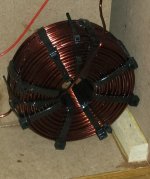
I use iron core, manually made of E + I core with an air gap (ur/u0 around 10 to 15), for the woofer when I need something around 2mH to 4mH.
Harmonics are below 48dB, which is the limit of my 8-bit scope and is good enough for me.
I also check the current limit observing the current as a function of time when applying a step voltage.
This was for a 200W system power @4ohms, so maximum peak current is 10A.
Saturation starts above 15A as shown below.

Oof. Is that a 1ohm resistor in parallel with the tweeter.Tweeter padding could be modified as well, series resistor belonging before filter and parallel part modded to match,
Window from 0 to 180 degrees is all that matters (the full Spinorama)
This speaker is for nearfield use only. It also uses an unconventional driver arrangement, which complicates things.we cannot see the whole picture
For those that peruse lots of threads, most of the details are familiar and make more sense. For anyone that hasn't seen them, details are available in other threads:
I think I'm about 3 months into this project so far but I'm now going to start the build thread.
This build consists of 3 way nearfield monitors and a coffee table that is also a push-push bass reflex subwoofer.
This is in no way an "optimal" build. It was never supposed to be. It is meant to be an outlandish, exotic, fun build. I wanted to use different drivers, different configurations, different methods, different everything. I can build a two studio monitor and have it play back accurate. This is not that. That I could just buy. This is building something you cannot just buy...
I'm having trouble with crossing this ribbon (GRS RT1.R) with this planar mid (GRS PT6825-8). I can cross them anywhere from 2k-8k and there ends up being a dip in response immediately once you go off axis even a few degrees. How can this be? I've modified my XO to be nearly all 4th order filters to try to keep them in phase. If I go any less, even a 3rd order, they will be in phase at the XO and then a few thousand hz later they will be out of phase and cancelling out. The same thing seems to happen to the mid and woofer crossover. The woofer is just a cone woofer. It is far less...
Last edited:
I also think that crossover is far from optimal, and has a big error in it, the impendance goes way to low in the treble. Your amp mostly can't handle impendance under 3ohm, so that should be avoided. And you can have a good response with way less parts, i"m very sure of that.
This speaker is for nearfield use only. It also uses an unconventional driver arrangement, which complicates things.
Ouch... I saw this project. In yet another thread. I remember it now! It has much more potential reasons to make a headache imo.
I saw the solid wall behind those speakers on some drawings, so still 90-180 degrees matter a little.
2 GRS speakers and 1 very specific use case subwoofer which is used as woofer, and again 1 GRS based subwoofer. And I see lots of stamped steel.
And very expensive cabinets. And then 25+ parts crossover...
Probably I stay silent for now on this thread.
On the positive side - I like the craftmanship of this project very much!
This is about the lowest you will get, but it costs:For lowest dcr but higher inductance coils use this
https://www.mundorf.com/audio/en/shop/Coils/EI_Coils/
Yet it is by far the most "unideal" component in a passive XO, being lossy, creating heat, suspect to vibrations/microphonics, interacts with other components (or anything magnetic), cores can saturate with sufficient current etc.'ve seen conflicting data. I've seen measurement that show significantly higher distortion, especially 3rd order and I've seen where it showed very low distortion difference with a claim of no audible difference
So it is the place where the money is best spent for quality imo.
Home made coils are less consistent in winding then machine made ones, the tightness will be less and variations will be larger in general.
The larger the diameter the more tricky it is to work with.
Last edited:
Back when North Creek Audio was still in business, I had them wind a pair of 8 gauge copper, 4.3mH air core inductors to replace the iron core for my Infinity RSIIb outboard crossovers. Large and very heavy, but they do sound good!
Attachments
The distortion in the woofer will approach 10% at Xmax, while a decent iron core inductor would still remain at your low level distortion figure at those levels.We are talking about 0.2% distortion max across the entire range of 100hz-35khz according to my low volume level measurements. Ehile still getting down to and F3 of 37 Hz.
At any rate, the loss of damping factor in the length of an air core with equivalent DCR to a decent iron core inductor would be of more concern to me than barely measurable (much less audible) hysteresis distortion.
IIR DSP works the same as passive crossovers, other than all the individual component headaches.If it weren't for the ribbon I'd be considering active even though I know very little about active outside of the DSP..
DSP could make any crossover type, delay, EQ and level matching easily configurable, as well as allowing for multiple presets for various listening levels.
Why would you consider the ribbon be a consideration against DSP?
Oh, I didn't see those. But OP should gave some context in this thread.This speaker is for nearfield use only. It also uses an unconventional driver arrangement, which complicates things.
For those that peruse lots of threads, most of the details are familiar and make more sense. For anyone that hasn't seen them, details are available in other threads:
OK, my verdict: Overly complicated crossover (unnecessary fourth-order filters, and maybe third-order also), dangerously low impedance, lack of 0 - 180 degrees measurements (although it is near-field monitor, back wall is in the nearfield also!) and too much wiggle in the tweeter frequency response (diffraction, maybe?).
What is "damping factor"? I have not heard this term before.At any rate, the loss of damping factor in the length of an air core with equivalent DCR to a decent iron core inductor would be of more concern to me than barely measurable (much less audible) hysteresis distortion.
Ribbons are, apparently, a dead short to the amplifier unless coupled with some passive components. At the very least, a capacitor.Why would you consider the ribbon be a consideration against DSP?
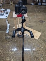
Gated measurements with a a calibrated mic and loopback reference. I took my own impedence data with the drivers in the enclosure.Can I ask some questions without making you mad? What are you currently using for an frd? Is it a gated measurement with a tail added, or something else? Did you measure the zma, or use factory data?
My experience with Sims is that on my speakers, they are never accurate. There's several reasons though, and not necessarily the fault of the software. ( I cut corners.)
My builds have come out to within 3 db of my simulations except for the low end which is almost impossible to simulate because of room gain and such. Most of the variation can be chocked up to room reflections and I cannot take a full range measurement without reflections.
If you want, I can send you all the measurements and you can take a whack at it. Maybe you can figure out a more simple crossover. I have all the measurements from 0-75 degrees. I didn't go all the way because it doesn't really matter when I sit within 30 degrees. The last measurements I took I only took to 60 degrees. The last 3 sets align almost perfectly so I know they are accurate. Measuring this unit was its own difficulty.Oh, I didn't see those. But OP should gave some context in this thread.
OK, my verdict: Overly complicated crossover (unnecessary fourth-order filters, and maybe third-order also), dangerously low impedance, lack of 0 - 180 degrees measurements (although it is near-field monitor, back wall is in the nearfield also!) and too much wiggle in the tweeter frequency response (diffraction, maybe?).
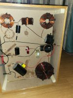
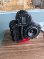
These pictures were taken before I changed the port design. The stand is also the port. All the interior volume is for the woofer. The tweeter has a protection back cup built in. The planar mid has a its own, quite large, back cup which is filled with damping material and a 3d printed diffuser. I tried 6 diffusers, this one works best.
Attachments
I don't know how to calculate that. I also don't know how to read that data. At what wattage could you hear the burr of the iron core?While considering cored inductors, try finding out under what circumstances would such one saturate.
Rarely do manufacturers mention any of this, and if so then insufficiently.
I did it once out of curiosity.
I've played with this for weeks in various way. I am pretty sure that dive is due to cancellation between the drivers due to their placement. The same thing happens with the mid and the woofer unless crossed exactly there and with those order of filters to prevent cacellation.Tweeter padding could be modified as well, series resistor belonging before filter and parallel part modded to match,
thereby preventing the 5 khz dive.
I can swap it and try it again but that dip never goes away. I've worked quite hard to minimize it.
This is good data to have. 48 db down seems like low enough it won't matter. This system will never see that kind of wattage so I think I'm good on the saturationI use iron core, manually made of E + I core with an air gap (ur/u0 around 10 to 15), for the woofer when I need something around 2mH to 4mH.
Harmonics are below 48dB, which is the limit of my 8-bit scope and is good enough for me.
I also check the current limit observing the current as a function of time when applying a step voltage.
This was for a 200W system power @4ohms, so maximum peak current is 10A.
Saturation starts above 15A as shown below.
Would you like to take a whack at it? I can send you all the data. Honestly, I very much hope you are right because this XO is going to be very expensive.I also think that crossover is far from optimal, and has a big error in it, the impendance goes way to low in the treble. Your amp mostly can't handle impendance under 3ohm, so that should be avoided. And you can have a good response with way less parts, i"m very sure of that.
Oh yes, this is an exercise in tearing my hair out. It was meant to be.Ouch... I saw this project. In yet another thread. I remember it now! It has much more potential reasons to make a headache imo.
I saw the solid wall behind those speakers on some drawings, so still 90-180 degrees matter a little.
2 GRS speakers and 1 very specific use case subwoofer which is used as woofer, and again 1 GRS based subwoofer. And I see lots of stamped steel.
And very expensive cabinets. And then 25+ parts crossover...
Probably I stay silent for now on this thread.
On the positive side - I like the craftmanship of this project very much!
I am pushing boundaries to see how complicated things can get and if I can still make it work.
This is kind of my thing. I like to do the hard things. My first build was a transmission line 3 way. While not that accurate accross its frequency response it does sound quite good.
It's the ratio of the speaker impedance (or the driver impedance) to the amplifier output impedance (and often speaker cable impedance). In this context, a higher wire resistance of the inductor is effectively in series with these other impedances, adding to the impedance of the amplifier (usually very low, like 0.1 ohm or less) and speaker cable (likewise, below 0.1 ohm) as seen by the woofer. This added resistance causes the amplifier to have less "control" of the woofer.What is "damping factor"? I have not heard this term before.
https://en.wikipedia.org/wiki/Damping_factor
- Home
- Loudspeakers
- Multi-Way
- Air Core vs Iron Core - Sensitivity