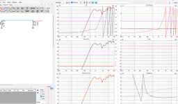
Here ya go. You really must model at least to 7 degrees on this one because otherwise there WILL be horrendous cancelations.I have a filter or two worked up using the original woofer frd. I would like to see the results with the revised one.
Attachments
-
Woofer_hor_deg+000.frd14.4 KB · Views: 22
-
GRS Ribbon.zma19.1 KB · Views: 26
-
GRS Planar.zma17.7 KB · Views: 28
-
Epique 5.5.zma18.7 KB · Views: 20
-
Mid_hor_deg+007.frd11.8 KB · Views: 25
-
Mid_hor_deg+000.frd9.9 KB · Views: 24
-
Tweeter_hor_deg+007.frd8.5 KB · Views: 26
-
Tweeter_hor_deg+000.frd8.5 KB · Views: 25
-
Woofer_hor_deg+007.frd14.4 KB · Views: 24
Something isn't right then. I just checked the tweeter files and the ones in the google drive are correct. Did you mix up the impedence data possibly?it is in the data that you gave me. This is the tweeter with no parts active, so open to the amp:
Attachments
They have resistors. I've done this on a few other builds and the amplifiers are fine. One system I did similar to I listen to for around 4 hours a day. Its been like that for 3 months. Still alive.what you did with your lrc filters parallel was creating shorts on certain frequencies that would kill most amplifiers. If you want to filter that passive you need a series lrc filter, that will have other negative effects. And as most don't hear that high anyway, it does not matter much. That kind of correction is typically done active (be it analog or dsp), not in a passive crossover.
Go check my original XO. It does have the issue but up until around 15 degrees you get no dip. I was able to achieve this. You said you could with less components, and yet, you did not.The midband dip is due to the aliggnment, that is almost impossible to get in phase over a wide frequencyband enough to avoid that. It's something you can try to eq out, but it will sound worse then when you don't because of phase issues you create. And the dip is small enough to not be hearable. But with the drivers and the alignment you use it's very hard to get a full neutral even dispertion sound, therefor the layout is not right. I told you that before in another tread about this speaker months ago.
That dip is definitely hearable. Thats a full 6 decibel dip over nearly 3,000 hz of range.
Yes, you did say the alignment was right. You suggested vertical alignment which would have had worse cancelations in the vertical range. This gives me cancelations in both the horizontal and vertical but to a far lesser degree. I don't sit in the same spot in my office chair. Sometimes I sit upright, sometimes I slouch, sometimes I lean back and listen. So your vertical alignment would have had horrendous cancelations if I did anything but sit start upright in my chair. I think we can all admit we don't sit stark upright in front of our computer at all times.
Thank you for this. Now I fully understand how to calculate DF. I may be able to tweak the system to use slightly smaller inductors. Without the 4th order there I will get a massive horizontal and vertical phase cancelation at the XO point within my listening window.n amp with 1000DF at 4 ohms would have an internal output impedance of .004 ohms.
Since your speakers are used at a desktop, lets ignore their minimal wire resistance effect on DF.
The two series iron core resistance (.39+.31+.004=.704 ohms) dropping DF to 9.9. Not great.
The two series air core resistance (1.1+.88+.004=1.94ohms) dropping DF to 2.016, which is very poor.
The insertion and DF losses make low frequency passive crossovers past second order a poor choice.
This build, like any other, is a series of trade offs. If I want them to fit underneath my monitors then this is the size they must be and to fit in that space they must be in this alignment. Its a tradeoff I am willing to make.
This is why I used a cheaper AB amplifier for the last two rounds of data collection. I didn't want the cap in because I wanted proper phase alignment. I was willing to kill this amplifier to get this proper data. Luckily, it did survive. Running it active for an amount of time I believe would kill it. For 10 sweeps I think just about any amplifier will survive.The ribbon transformer presenting near a dead short at DC may be a problem for many amps, and the use of a capacitor while testing changes the phase response
I used just the on axis measurements....But I designed with toe in. These results show from 9 degrees to 30 degrees. I figure that's a reasonable range. Everything in between, is in between these two lines, and it transitions smoothly. The tweeter, and mid will change slightly at these angles, but I think with some tweaking, a suitable compromise can be had.
Attachments

That looks really good. What are the component values and schematic? Also, what program is this you are using? I've seen it in some how to videos but I've never figured out what it is.I used just the on axis measurements....But I designed with toe in. These results show from 9 degrees to 30 degrees. I figure that's a reasonable range. Everything in between, is in between these two lines, and it transitions smoothly.
Welter,Amplifier damping factor (DF)is defined as “the ratio of the load impedance (loudspeaker plus wire resistance) to the amplifier internal output impedance.” The DF indicates the amplifier’s ability to control overshoot of the loudspeaker, i.e., to stop the cone from moving.
A DF of 200 at 4 ohms would be considered quite good, and anything over ~50 makes little difference.
If the DF of the entire loudspeaker/wire/series inductors/amplifier circuit is very low, say ~10, it will exhibit poor definition in the low frequency range. Low frequency transients such as kick drum hits will sound “muddy” instead of that crisp “punch” most want from the system. Generally ~20DF is considered to be the lower limit of "hi-fi", though some like the round, boomy sound of low DF.
An amp with 1000DF at 4 ohms would have an internal output impedance of .004 ohms.
Since your speakers are used at a desktop, lets ignore their minimal wire resistance effect on DF.
The two series iron core resistance (.39+.31+.004=.704 ohms) dropping DF to 9.9. Not great.
The two series air core resistance (1.1+.88+.004=1.94ohms) dropping DF to 2.016, which is very poor.
The insertion and DF losses make low frequency passive crossovers past second order a poor choice.
The ribbon transformer presenting near a dead short at DC may be a problem for many amps, and the use of a capacitor while testing changes the phase response.
View attachment 1418109
Best of luck getting to the cause of your ribbon tweeter measurements exhibiting far too many 360 degree phase rotations within it's pass band.
Art
If I ditch the air cores and go with Super Q inductors the price is nearly the same but I end up with MUCH lower damping factor and the sensitivity of the entire system goes up significantly. This seems well worth it.
3.5mh Super Q has a DCR of 0.09
2.5mh Super Q has a DCR of 0.073

If you have the schematic, can you insert the off axis measurements automatically? This would probably need to use the 15 degree measurements rather than the on axis, but with these drivers, I don't think it will change drastically. The top end may droop, but as you can see in the transfer functions, it should be easy to bring it back up with a resistor change..
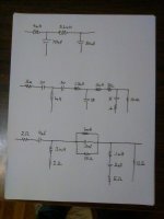
Simple crossover:


Impedance is usefully high.
With one additional RLC notch filter at 3 kHz:


Off axis frequency response is slightly worse than 4th order crossover (post #1), but the crossover cost is significantly lower.
Much better is the free solution: put tweeter and mid planar drivers in the same vertical line, one above other - no need for 4th order crossover!
Impedance is usefully high.
With one additional RLC notch filter at 3 kHz:
Off axis frequency response is slightly worse than 4th order crossover (post #1), but the crossover cost is significantly lower.
Much better is the free solution: put tweeter and mid planar drivers in the same vertical line, one above other - no need for 4th order crossover!
The damping factor would be MUCH higher, which is a good thing, low damping factor (and sensitivity) sucks.If I ditch the air cores and go with Super Q inductors the price is nearly the same but I end up with MUCH lower damping factor and the sensitivity of the entire system goes up significantly. This seems well worth it.
3.5mh Super Q has a DCR of 0.09
2.5mh Super Q has a DCR of 0.073
Assuming a 4 ohm woofer impedance and an amplifier DF of 1000, the above series resistance would make the DF ~24.
With an an amplifier DF of 200, the above series resistance would make the DF 22, still in the "OK" range.
What is the price of those four ERSE Super Q inductors?
The 3.5 is $31 vs $20 for an air coreWhat is the price of those four ERSE Super Q inductors?
https://uscoils.us/product/ussq55-12-2500/
The 2.5 is also $31
Granted. These are 12 awg. They also have 14 awg which gives similarly low DCR as the 12 awg. I think its worth it for a system like this so that the whole thing is easier to drive. It also flattens out the entire low end. I think the DCR of my other system is why I always have a bump a bass. I'm changing the Q of the woofers with inductors that have high DCR. Guess I learned another place where the extra $$$ is well spent.
I've found a lot of hobbies is just trying to figure out what is worth it and what isn't.
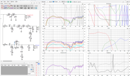
Inserted. What am I missing here? This seems far off.If you have the schematic, can you insert the off axis measurements automatically? This would probably need to use the 15 degree measurements rather than the on axis, but with these drivers, I don't think it will change drastically. The top end may droop, but as you can see in the transfer functions, it should be easy to bring it back up with a resistor change..
Attachments
I would keep the resistance of the air cores. It reduces distortion.
If you mind the loss of efficiency a bucking same size magnet to the drivers gives you up to 1.5db extra efficiency. And lowers audibly the Q a bit.
If you mind the loss of efficiency a bucking same size magnet to the drivers gives you up to 1.5db extra efficiency. And lowers audibly the Q a bit.
Your impedence is much better than mine. I'll have 3 hours on a plane tomorrow to take a look at what you did differently with your values to get your impedence up so much higher than mine.Off axis frequency response is slightly worse than 4th order crossover (post #1), but the crossover cost is significantly lower.
Much better is the free solution: put tweeter and mid planar drivers in the same vertical line, one above other - no need for 4th order crossover!
Yes, your off axis is much worse. I am going to notice that even just sitting in my chair. You very much did achieve similar on axis with far less components.
I'm going to try and fiddle with the values on mine. Try and incorporate some of the work you have on yours. Maybe I can get my impedence up a bit. I use relatively cheap amplifiers so I am not so concerned with frying one. It only dips to 1.8 ohm at its lowest so I'm not too worried about killing one. That said, I have a bad habit of getting low impedence ranges near my crossover points and need to rectify that.
I think adding in the Super Q coils in the woofer series is well worth the extra sensitivity and higher damping factor. I plan to keep this system for a long time and with the crossover components being exposed on the wall of my office.... I don't think having the extra components is a bad thing here. I might just order all the caps through my work digikey account. Technically I have an office setup budget to use and I have only used half of it to kit the office out so far. I could spend some of that money on caps.
I'm seeing a lot of data showing its a tiny amount of distortion at lower levels. You think that is worth an extra 3 db of sensitivity? I'd almost think that would lower distortion would be offset by the amplifier having to put out more power. The more power an amplifier puts out the higher its distortion right?I would keep the resistance of the air cores. It reduces distortion.
If you mind the loss of efficiency a bucking same size magnet to the drivers gives you up to 1.5db extra efficiency. And lowers audibly the Q a bit.
What is a "bucking same size magnet"? I don't understand what you are saying there.
Resistances in crossovers lower the distortion. I refer to the "simple resistor method" for current drive by Esa Merilainen. Look for current drive. Nelson Pass did tests with this simple resistor method and documented it.
Buy a same size magnet and glue it to the backside of the magnet. Search in the forum you will find explanations how to do. It must be a ringmagnet with polarity for loudspeakers
The magnet first gives resistance and then attracts. Take care to center well and let contact glue dry respecting dry time for good fixation. Maybe try first with a spare driver to train how to do.
You can expect at best +1.5 db more.
Air-core inductors for woofer low-pass filter is wasting money and efficiency. Woofer distortion is much higher than iron core distortion.I would keep the resistance of the air cores. It reduces distortion.
- Home
- Loudspeakers
- Multi-Way
- Air Core vs Iron Core - Sensitivity