I could if i had time, but my time is limited. You won't get a result today i think, it will be more tomorrow or in the weekend.Would you like to take a whack at it? I can send you all the data. Honestly, I very much hope you are right because this XO is going to be very expensive.
Don't forget > driver efficiency, power through the XO and desired SPL all play a part in whether iron core's are suitable.Then I would skip iron cores for indictors. They distort...
/
It is only upon saturation that iron core's distort, and there are high power irons available 🙂

I don't know how to calculate that. I also don't know how to read that data. At what wattage could you hear the burr of the iron core?
I don't remember at what exact voltage have I heard it.
It was a simple series circuit of one resistor and an inductor. Signal was 100 Hz sine.
Under each driving voltage, I measured with multimeter the voltage drops, one across resistor,
and one across inductor. Put them into formula and you get inductance value.
I had two 10W cement 8R2 resistors in parallel, and I did the measurement quickly, not
to fry these. Resistor dissipation was 3x higher than rating.
edit: btw, why don't you attach the frd's and zma's, and someone may take a look at it?
Last edited:
Good article!
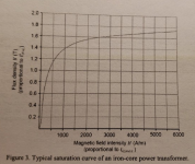
It proves that if we keep B (Magnetic Field) below the value where saturation starts, the other effects on THD, such as hysteresis and non linear BxH curve, are minimum.
Calculating B is simple and Bmax of each material is a known value.
The knee starts around 1T for laminated steel and 0.3 for ferrite (see curve below).
Calculating B as function of L (inductance), I (current), N (turns) and A (area)
B=(L*I)/(N*A)
Example:
L=0.003H (inductance)
I=10A (peak current)
N=89 (number of turns)
A=0.0004m2 (core area - 20cm x 20cm this is the core section area of the 12V/1A transformer as an example)
B=(0.003*10)/(89*0.0004)
B=0.84T
This core can handle up to 10Apeak without saturation and this means 7Arms which means P=4*7^2=196W @4ohms.
It will not saturate.
Note that if we use ferrite in this case above, it would start to saturate with only 3A.
But, if this inductor is for a mid-rante in a lower power system where it only needs 2Apeak, it will be ok to use ferrite, since B would be 0.17T.
Attachments
Yes, please!If you want, I can send you all the measurements
Yes, all of them please!I have all the measurements from 0-75 degrees.
It will matter if there is a wall immediately behind the loudspeaker.it doesn't really matter when I sit within 30 degrees.
No. The low impedance at 5 kHz is solely due to crossover/filter design.I am pretty sure that dive is due to cancellation between the drivers due to their placement.
I can take the measurements in place when I get home. Right where they will sit on the desk.It will matter if there is a wall immediately behind the loudspeaker.
There will be bounce off the desk and there will be bounce from the frequencies coming out of the rear firing port. How do I gate this? I normally merge near and far field field in the 200-300 hz range. WIth it on the desk it will bounce around the 1500-2500hz range. I know this because of when I measured my friend's studio monitors at his mixing studio. It bounces at whatever frequency is the length between the speaker and the first solid object.
Incoming. I am zipping it up right nowedit: btw, why don't you attach the frd's and zma's, and someone may take a look at it?
So, just to clarify, the frd files have not been altered on the low end by splicing on a close mic measurement, or anything, right?Gated measurements with a a calibrated mic and loopback reference. I took my own impedence data with the drivers in the enclosure.
My builds have come out to within 3 db of my simulations except for the low end which is almost impossible to simulate because of room gain and such. Most of the variation can be chocked up to room reflections and I cannot take a full range measurement without reflections.
I still have my sim on the computer using the woofer file that has the port resonance. If you have a new file, I might play with it a little more. My previous sim was pretty involved too. Lots of parts, but laid out different than yours, which is to be expected.
I guess what I was thinking when I made the comment about the sim results not being accurate was the notion that the more complex the filters are, the less accurate the sim results might become. I was also hinting that some trial and error would be needed once you get some parts. Maybe a lot. If you post a new woofer frd, I'll see what I can come up with.
Here are the latest measurements. I have taken full degree measurements but this is only from 0-60 degrees. I took them actually in 7 degree increments for the beginning range as that is the range I was most interested in. I spent like an hour making sure this was all aligned so that the mic was positioned EXACTLY in the middle of each driver when the measurements was taken. I used a 3d printed mic holder for this. These are gated and referenced measurements so they include the Z offset and the diffraction data. I do realize now that VituixCAD only allows 5 degree increments but if you load the 7 degree increments it models it just fine. The older measurements use a slightly different port design (I'm on version 18 of the port design) so they would not be accurate if I share them with you all.
SPL is not calibrated so the levels of the far field are just for reference of the drivers to one another
You should be able to merge them around the 200 hz mark. I have a large shop and I take these measurements high up in the air away from any hard surfaces. Reflections shouldn't show up until the 200hz mark. The mid shouldn't need any gating. It was taken from 150-40khz. I didn't want to blow it up. The tweeter was taken from 800-40khz, also, didn't want to blow it up.
Ribbon was taken raw, no cap in line. I used an AB amplifier.
There are two port measurements. One is 5mm inside the of the port tube. One is 5mm inside the flare of the port. The port is 160mm behind the woofer rear firing.
Driver and port dimension offsets are in the two screenshots.
You'll see that these drivers are quite a handful. I really do hope someone sees something I do not. The order of filters I chose was for phase alignment purposes. Using lesser order leads to cancelations along the frequency range. Of course, it is very possible I am just really bad at this. I have only been doing this for one year and it was a steep learning curve. I have included my current XO.
I err on the side of dips instead of peaks. Personally, I would rather have a dip in my frequency response than a peak that makes the system sound harsh.
https://drive.google.com/drive/folders/1WXKYH-eEpO94KTkG_rVK3DbdrxDhAHiq?usp=drive_link
Let me know if the link opens for you. The MDAT files, even compressed, are too large for the server limit.
Most importantly, have fun!
Last edited:
It's posted. Even the raw mdat are there. Have at it!So, just to clarify, the frd files have not been altered on the low end by splicing on a close mic measurement, or anything, right?
I still have my sim on the computer using the woofer file that has the port resonance. If you have a new file, I might play with it a little more. My previous sim was pretty involved too. Lots of parts, but laid out different than yours, which is to be expected.
I guess what I was thinking when I made the comment about the sim results not being accurate was the notion that the more complex the filters are, the less accurate the sim results might become. I was also hinting that some trial and error would be needed once you get some parts. Maybe a lot. If you post a new woofer frd, I'll see what I can come up with.
I'm having computer issues with the link. Could you post just the woofer frd like before. Just the on axis please.
I'll look at it when I get back and post the frd files separatelyI'm having computer issues with the link. Could you post just the woofer frd like before. Just the on axis please.
I did some quick check while waiting for a computer to update (i'm an IT guy) and got it fast a lot better. Due to the layout of your drivers directivity is hard to get right, but at least frequency on axis and phase are right here, with less parts and not a to low impendance anywhere in the band. It's not fully right yet (i need more tinkering time and so) but it's a good start to work further on i think.

I started from scratch to be honest, the file is uploading, i'll post a link later...
I started from scratch to be honest, the file is uploading, i'll post a link later...
You still have huge dips as soon as you're 10 degrees off axis. Something my XO does not have.I did some quick check while waiting for a computer to update (i'm an IT guy) and got it fast a lot better. Due to the layout of your drivers directivity is hard to get right, but at least frequency on axis and phase are right here, with less parts and not a to low impendance anywhere in the band. It's not fully right yet (i need more tinkering time and so) but it's a good start to work further on i think.
View attachment 1418022
I started from scratch to be honest, the file is uploading, i'll post a link later...
Also, your mid has 5 db of variance.
The tweeter drops off at 15k. That cannot be right. This tweeter should play right up to 40khz.
Now you are starting to understand what I accomplished before.
I have a filter or two worked up using the original woofer frd. I would like to see the results with the revised one.
it is in the data that you gave me. This is the tweeter with no parts active, so open to the amp:

what you did with your lrc filters parallel was creating shorts on certain frequencies that would kill most amplifiers. If you want to filter that passive you need a series lrc filter, that will have other negative effects. And as most don't hear that high anyway, it does not matter much. That kind of correction is typically done active (be it analog or dsp), not in a passive crossover.
The midband dip is due to the aliggnment, that is almost impossible to get in phase over a wide frequencyband enough to avoid that. It's something you can try to eq out, but it will sound worse then when you don't because of phase issues you create. And the dip is small enough to not be hearable. But with the drivers and the alignment you use it's very hard to get a full neutral even dispertion sound, therefor the layout is not right. I told you that before in another tread about this speaker months ago.
btw, my crossover was a 5 min tinkering, not a full detailed work out. I need more time in front of the right computer for that.
Amplifier damping factor (DF)is defined as “the ratio of the load impedance (loudspeaker plus wire resistance) to the amplifier internal output impedance.” The DF indicates the amplifier’s ability to control overshoot of the loudspeaker, i.e., to stop the cone from moving.What is "damping factor"? I have not heard this term before.
A DF of 200 at 4 ohms would be considered quite good, and anything over ~50 makes little difference.
If the DF of the entire loudspeaker/wire/series inductors/amplifier circuit is very low, say ~10, it will exhibit poor definition in the low frequency range. Low frequency transients such as kick drum hits will sound “muddy” instead of that crisp “punch” most want from the system. Generally ~20DF is considered to be the lower limit of "hi-fi", though some like the round, boomy sound of low DF.
An amp with 1000DF at 4 ohms would have an internal output impedance of .004 ohms.
Since your speakers are used at a desktop, lets ignore their minimal wire resistance effect on DF.
The two series iron core resistance (.39+.31+.004=.704 ohms) dropping DF to 9.9. Not great.
The two series air core resistance (1.1+.88+.004=1.94ohms) dropping DF to 2.016, which is very poor.
The insertion and DF losses make low frequency passive crossovers past second order a poor choice.
The ribbon transformer presenting near a dead short at DC may be a problem for many amps, and the use of a capacitor while testing changes the phase response.Ribbons are, apparently, a dead short to the amplifier unless coupled with some passive components. At the very least, a capacitor.
Best of luck getting to the cause of your ribbon tweeter measurements exhibiting far too many 360 degree phase rotations within it's pass band.
Art
- Home
- Loudspeakers
- Multi-Way
- Air Core vs Iron Core - Sensitivity