Thanks McTavish. I'm using 47uF as the first cap. So, a 50R (~10W) resistor in series before the rectifier should be ok ?
That should be fine, just make sure that there is one in each leg of the high voltage winding. Also make sure that there's plenty of ventilation room around them, they will get relatively hot in use.
Looks like I made a mistake with the trafo specs. I was looking at the tubelab page and followed the 0-6.3v, 0-5v and 310-0-310 secondaries.
Is there a way to wire this with the TSE-II boards ?
Is there a way to wire this with the TSE-II boards ?
Last edited:
sunil that trafo generally looks good, which issue do you have that?
310V may be end up a bit low but overall I think that should work well.
310V may be end up a bit low but overall I think that should work well.
The 6.3v & 5v taps are not centre tapped. Georges site mentions not required, but going through the posts here, I realized mostly everyone has got C.T. Confused on how to go about wiring it 😕
6.3V CT is only needed for 45's and 2A3. 5V CT is not needed in either case.
From tubelab.com, for 300B:
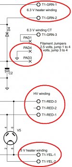
5V go to T1-YEL
6.3V go to T1-GRN 1 and 2 (i.e the 3rd pad from the top is not used)
Jumper pads 3 and 4 on the PCB for 5V filament needed for 300B.
From tubelab.com, for 300B:
The power transformer needs to provide about 640 or 650 volts center tapped at 150 mA or more, 5 volts at 2 amps, and 6.3 volts at 4 amps. A center tap on the 6.3 volt winding is NOT required.
5V go to T1-YEL
6.3V go to T1-GRN 1 and 2 (i.e the 3rd pad from the top is not used)
Jumper pads 3 and 4 on the PCB for 5V filament needed for 300B.
Thank you itsikhefez.
So the connection is like this. Please ignore the color coding I've used.
So the connection is like this. Please ignore the color coding I've used.
Attachments
Last edited:
Almost.
You need T1_GRN 1 & 2, not 2 & 3.
This is info is also available in the file `TSE_II_schematic.pdf` attached to the first post of this thread
You need T1_GRN 1 & 2, not 2 & 3.
This is info is also available in the file `TSE_II_schematic.pdf` attached to the first post of this thread
Yeah, just saw that. The third pin from the 'TOP' is to be ignored. Thanks again.
Cheers.
Cheers.
Attachments
Last edited:
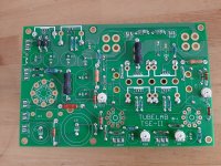
Wired the ICs and when checking the work found pins on IC1 & IC2 showing continuity on terminals 2 & 3, (A & K). There is no solder bridging the terminals on the board for sure.
I got a spare pair and those are showing continuity as well. Is this normal, are the ICs fake /busted or is this expected ?
I got a spare pair and those are showing continuity as well. Is this normal, are the ICs fake /busted or is this expected ?
Last edited:
TSE-II (300B) - replacement for IC1 & IC2 - DN2540
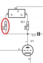
Been through the various threads and DN2540 is the recommended replacement. Am I right in understanding R16 & R27 have to change - 180R.
George post from the TSE thread. Can you please help confirm ? Does carbon comp here make a difference ?
10m45s
Been through the various threads and DN2540 is the recommended replacement. Am I right in understanding R16 & R27 have to change - 180R.
I have used the DN2540 in a TSE. I think I used a 180 ohm resistor. The DN2540 is rated for 400 volts but you will always drop at least 50 volts in the 5842, usually 150 to 200. That way the DN2540 sees about 250 volts.
The 5842 will dissipate too much power if cranked to 27 mA. I aim for 10 to 15 mA which keeps the dissipation to 3 watts if the plate voltage drifts to 200 volts with age. The 5842 has a wide tube to tube variation and does tend to drift with age.
George post from the TSE thread. Can you please help confirm ? Does carbon comp here make a difference ?
10m45s
Attachments
Wired the ICs and when checking the work found pins on IC1 & IC2 showing continuity on terminals 2 & 3, (A & K).
I measured some new, known good 10M45's and also see "continuity" between A and K, so this appears to be normal. The readings are slightly different when the probes are swapped, and vary depending on which meter I use.
A carbon comp resistor is not needed on the 10M45.
The only place a CC resistor seems to be needed is on the grid of the 5842. Some people report that a carbon film or metal film resistor works on the grid, but I have seen some tubes oscillate with a metal film resistor.
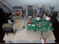
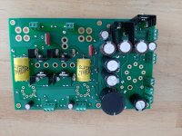
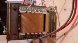
I started building my TSE-II about 2 weeks ago. I have it working now on a piece of plywood on my Klipsch Cornwall speakers and have to say it sounds really good, so very happy with the result so far.
I tried to use transformers that I allready had and ended up with an AE power transformer running off the 300-0-300 taps and combined with a Philips choke that measures 7H and a DCR of 27 ohms gives a B+ of about 375V +/- 4V depending on the line voltage.
I had to use a separate 5V transformer, because there was no 5V tap. It puts out AC 5.5V so I had to put a 0.22 ohm resitor in to get it to 5.08V, need to find a slightly larger resitor.
I have the 300B tubes set at about 62 mA, not sure if I should try raising this a bit more.
Output transformer are also from AE, but a bit of a mystery. They are probably 5K and 50W according to AE, but they can not be 100% sure because these do not have an AE part number they can look up. Primary connections are labeled 0 (B+) and V g2, so thats weird. They make the big Edcor opt's I have on my SSE look small.
The only small issue I had was that the filaments of the 5842 tubes only got 5.82V. I found an old thread and it suggested lowering R3. I now have 1.5 Ohm in there and the voltage went up to between 6.1 or 6.2V. I will try a 1.3 or 1.4 ohm resitor later, but for now it's good enough.
Still need to make a case, but that may take some time because I am stil playing the amp now. It will be a very heavy amp since everything is a bit oversized.
Attachments
Hello!
Nice work and thank you for thé Very good pics, it could help when I’ll built mine.
Gilles
Nice work and thank you for thé Very good pics, it could help when I’ll built mine.
Gilles
I started building my TSE-II about 2 weeks ago. I have it working now on a piece of plywood on my Klipsch Cornwall speakers and have to say it sounds really good, so very happy with the result so far.
I tried to use transformers that I allready had and ended up with an AE power transformer running off the 300-0-300 taps and combined with a Philips choke that measures 7H and a DCR of 27 ohms gives a B+ of about 375V +/- 4V depending on the line voltage.
I had to use a separate 5V transformer, because there was no 5V tap. It puts out AC 5.5V so I had to put a 0.22 ohm resitor in to get it to 5.08V, need to find a slightly larger resitor.
I have the 300B tubes set at about 62 mA, not sure if I should try raising this a bit more.
Output transformer are also from AE, but a bit of a mystery. They are probably 5K and 50W according to AE, but they can not be 100% sure because these do not have an AE part number they can look up. Primary connections are labeled 0 (B+) and V g2, so thats weird. They make the big Edcor opt's I have on my SSE look small.
The only small issue I had was that the filaments of the 5842 tubes only got 5.82V. I found an old thread and it suggested lowering R3. I now have 1.5 Ohm in there and the voltage went up to between 6.1 or 6.2V. I will try a 1.3 or 1.4 ohm resitor later, but for now it's good enough.
Still need to make a case, but that may take some time because I am stil playing the amp now. It will be a very heavy amp since everything is a bit oversized.
Hi Debije, hows the heat on the regulator and R36. My PS and choke is similar (310-0-310) and 7H (~80R though) , just wondering what you're getting. Is the 6.5w on R36 enough? I have a 10W cement resistor (white coffin) there.
Last edited:

- Home
- More Vendors...
- Tubelab
- After a 14 year run, the TSE must DIE!