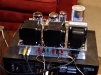
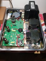
Fixed the regulator and made a L-brace of sort for the heatsink. The regulator is not directly attached to the heatsink. Will this work ? Should I look at some other way to heatsink. Not sure if this is a good idea or if it will even work.
The HS is 1.5" x 1" and 2.5" height. Can someone please comment ?
The HS is 1.5" x 1" and 2.5" height. Can someone please comment ?
Attachments

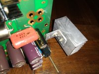
The general concept looks workable, but the "L-Brace" needs to be thicker and aluminum to be able to conduct the heat from the regulator to the heatsink.
It is just a gut feeling, but I would make it from 1/8" or thicker material. Also make sure that the surfaces at all of the contact points (regulator to L-Brace and L-Brace to Heatsink) are as flat as you can get them and put the required electrical insulator pad thermal paste at the joints to promote heat transfer. Also I am assuming that the weight of the heatsink will not be permanently supported by the regulator.
It is just a gut feeling, but I would make it from 1/8" or thicker material. Also make sure that the surfaces at all of the contact points (regulator to L-Brace and L-Brace to Heatsink) are as flat as you can get them and put the required electrical insulator pad thermal paste at the joints to promote heat transfer. Also I am assuming that the weight of the heatsink will not be permanently supported by the regulator.
My opinion is that it's overkill.
If you're going to send it to Mars, or use it for military hardware, it's going to break.
Use one of these.
Those are the same heat sinks i am using on my build and I have had no issues with heat even on 100 degree days with no ac.
The general concept looks workable, but the "L-Brace" needs to be thicker and aluminum to be able to conduct the heat
from the regulator to the heatsink.
It is just a gut feeling, but I would make it from 1/8" or thicker material. Also make sure that the surfaces at all of the contact points
(regulator to L-Brace and L-Brace to Heatsink) are as flat as you can get them and put the required electrical insulator pad thermal paste at
the joints to promote heat transfer. Also I am assuming that the weight of the heatsink will not be permanently supported by the regulator.
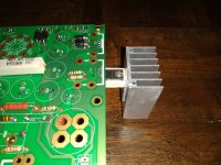
Thanks csample. I had the same doubts on the contact between the HS & the brace. Decided to try another HS. When the board fires up fine,
I will solder a support from the HS back to the board, right now its hanging of the regulator.
My opinion is that it's overkill.
If you're going to send it to Mars, or use it for military hardware, it's going to break.
Use one of these.
Those are the same heat sinks i am using on my build and I have had no issues with heat even on 100 degree days with no ac.
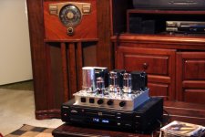
Thanks Duke58 /brl0301. Duke58 - your pic looks like the SSE. Same kind of heat ?
Attachments

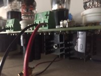
Anyone else see the obvious problem in Sunil's board?
The board is a TSE-II, but the regulator chip seen on the heat sink is a Sharp part for the original TSE board. These are not pin compatible, nor completely electrically compatible. The TSE-II board should use the Microchip MIC29502WT part as listed in the BOM on the first page of this thread. Several other parts, mostly resistors have changed in the new version as well.
Note, that someone who knew exactly what they were doing could probably make the Sharp part work in this board, but it would take some work. I have not tried this, but I did make the new Microchip part, and several other possible choices work in the original TSE board during the early testing of the new design. It did involve a bit of lead bending and shrink tubing.
It's a TSE-II. The Raytheon 5842 is the obvious give-away. SSE's only have one small heat sink, and the board will work without any heat sink at all, but the chip may fry in a hot closed box environment. I had one unsolder itself early on. It was still alive and is still working today.
The board is a TSE-II, but the regulator chip seen on the heat sink is a Sharp part for the original TSE board. These are not pin compatible, nor completely electrically compatible. The TSE-II board should use the Microchip MIC29502WT part as listed in the BOM on the first page of this thread. Several other parts, mostly resistors have changed in the new version as well.
Note, that someone who knew exactly what they were doing could probably make the Sharp part work in this board, but it would take some work. I have not tried this, but I did make the new Microchip part, and several other possible choices work in the original TSE board during the early testing of the new design. It did involve a bit of lead bending and shrink tubing.
Thanks Duke58 /brl0301. Duke58 - your pic looks like the SSE.
It's a TSE-II. The Raytheon 5842 is the obvious give-away. SSE's only have one small heat sink, and the board will work without any heat sink at all, but the chip may fry in a hot closed box environment. I had one unsolder itself early on. It was still alive and is still working today.
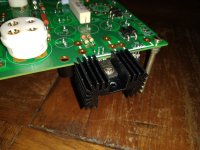
Using 45 output tubes with 5842 driver tubes- no problems with my TSE-II overheating or any other problems. Note that I am using the Microchip regulator chip on an inexpensive heatsink available from Digikey, Mouser, etc.
Also, if you're concerned about heat, I suppose you could use the Sharp chip with the big aluminum heatsink if you are not going to move the amp around.
Also, if you're concerned about heat, I suppose you could use the Sharp chip with the big aluminum heatsink if you are not going to move the amp around.
Anyone else see the obvious problem in Sunil's board?
The board is a TSE-II, but the regulator chip seen on the heat sink is a Sharp part for the original TSE board. These are not pin compatible, nor completely electrically compatible. The TSE-II board should use the Microchip MIC29502WT part as listed in the BOM on the first page of this thread. Several other parts, mostly resistors have changed in the new version as well.
Note, that someone who knew exactly what they were doing could probably make the Sharp part work in this board, but it would take some work. I have not tried this, but I did make the new Microchip part, and several other possible choices work in the original TSE board during the early testing of the new design. It did involve a bit of lead bending and shrink tubing.
It's a TSE-II. The Raytheon 5842 is the obvious give-away. SSE's only have one small heat sink, and the board will work without any heat sink at all, but the chip may fry in a hot closed box environment. I had one unsolder itself early on. It was still alive and is still working today.
Thanks George. I completely missed the Sharp part as being incompatible in the TSE-II. The resistors and caps are what was in the first page BOM. 🙁
What a bummer !
Last edited:
Using 45 output tubes with 5842 driver tubes- no problems with my TSE-II overheating or any other problems. Note that I am using the Microchip regulator chip on an inexpensive heatsink available from Digikey, Mouser, etc.
Also, if you're concerned about heat, I suppose you could use the Sharp chip with the big aluminum heatsink if you are not going to move the amp around.
Our summers can get hot, so I'm being cautious I guess. Once I get the Microchip regulator I'll use the heatsink from the last photo (black).
I suppose you could use the Sharp chip with the big aluminum heatsink if you are not going to move the amp around
The heat sinks specified in the parts list should work fine for most applications. 2A3 tubes are the electrical worse case since a pair will draw 5 amps of combined heater current. With a high line voltage and a power transformer that's generous with over voltage, you could be burning about 10 watts in that regulator chip. This is a problem with any heat sink that is entirely enclosed in a box with no ventilation, since that heat has nowhere to go and gets trapped inside the box. Even a lower powered amp will eventually heat up an enclosed box if the heat can't escape.
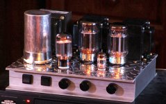
Here is an example of what NOT to do. I built this SSE in 2006. It was the first one I built into a chassis. It has worked flawlessly for 14 years and served as the amp for my "computer speakers" for about 3 years. They were Yamaha NS-10's and my computer also had full MIDI and audio recording capability, guitar, microphone and keyboard inputs, and even a turntable connected to it. This amp was on whenever my PC was on, even if music was not playing.
The SSE ran KT88's and got HOT. The power transformer would be too hot to touch after 6 or 8 hours, yet the amp never faltered, and still had the same tubes in it when it was packed up to move in 2014. Unfortunately is was dropped during the move, and looks rather out of shape today....but it STILL WORKS! The PC board is a bit discolored though. This is the amp where one of the 10M45's unsoldered itself.
Note that when placed on a flat surface there is no place for any heat to escape the box. The cathode resistors alone generate about 8 watts of heat.
Attachments

A few questions as I work to finish my TSE-II build
I was wondering if somebody could answer a couple questions for me: I am in the US, using 120V mains.
1) What is the present thought on using CL-90 thermistors on the input wiring? None, one CL-90 on the Live ac wire to one side of the primary, or one CL-90 on each Live and Neutral to both windings of the primary of the power transformer?
2) My amp will be 300b output using a 5ar4 rectifier, will a 2A slo blo fuse typically be adequate?
3) I normally use a ground lift circuit ( bridge rectifier, 10 ohm resistor, 0.1uf cap) between signal and chassis ground. Is it ok in this circuit, or should I just use another CL-90, or go direct non-elevated ground between signal and chassis ground?
Thanks,
Matt
All good questions. Personally I only use thermistors on solid state rectified power supplies. As for fusing, I have an organ chassis here that uses a pair of fuses in series. One small slo blo and a larger fast acting. I always thought that was a pretty clever way to protect both transformers and tubes in a push pull design.
To answer your question, I’m using a 2 amp fast acting in mine. It runs at about 3/4 amp at idle so you could go lower. Since class A draws peak current at idle, unlike push-pull, I can’t see the advantage to a slo blo. Perhaps someone can enlighten me.
To answer your question, I’m using a 2 amp fast acting in mine. It runs at about 3/4 amp at idle so you could go lower. Since class A draws peak current at idle, unlike push-pull, I can’t see the advantage to a slo blo. Perhaps someone can enlighten me.
Last edited:
I just noticed your 300B comment. Mine is a 45 build and your mileage will definitely vary. Your heater current and plate current will both be higher.
All good questions. Personally I only use thermistors on solid state rectified power supplies. As for fusing, I have an organ chassis here that uses a pair of fuses in series. One small slo blo and a larger fast acting. I always thought that was a pretty clever way to protect both transformers and tubes in a push pull design.
To answer your question, I’m using a 2 amp fast acting in mine. It runs at about 3/4 amp at idle so you could go lower. Since class A draws peak current at idle, unlike push-pull, I can’t see the advantage to a slo blo. Perhaps someone can enlighten me.
doesnt the slow blow help with the inital start up surge of the rectifier charging any ps caps?
Bigger problem as I check my TSE-II
Hi, started testing my TSE II board, and all checks out with the negative bias supply, and both the 5 vdc fils to the 300b sockets and 6v3 dc voltage to the 5842 sockets. Voltages are as expected including correct AC voltage to pins 4 and 6 of the rectifier socket, and 5vac to pins 2 and 8.
The problems start when I put in a 5ar4 tube and check for B+. 2A fuse blew almost immediately, and my current limiting 2A variac tripped. 5ar4 is known good. Near short is noted with even a couple volts on the variac with the rectifier tube in circuit.
There is almost a dead short in the supply circuit. I checked all connections to the board, no caps are shorted or backwards, no solder bridges, etc and all is correct.
I usually check all my components for correct values, and did so with this build, except for the CCS ICs and mosfets.
When I checked the other pair of unused STF3LN80K5 mosfets I got in the same order, they are bad, I only get the diode function to check out. Drain to source connection stays open.
Will these bad mosfets account for the near short circuit noted?
I have new mosfets on order from another vendor, as I am afraid of the same thing happening with the same batch if I get them from digikey again.
I was planning on just replacing the mosfets and then checking to see if the short is fixed with this approach, unless someone suggests other things to check out.
Matt
"I was planning on just replacing the mosfets and then checking to see if the short is fixed with this approach, unless someone suggests other things to check out."
That's what I would do...
That's what I would do...
A new TSE-II
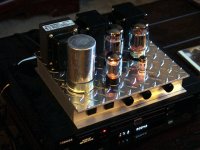
Happy to report a new TSE-II is up and running.
Some photos, details and a couple questions :
300B – Emission Labs
I can say now they sound warm, detailed, super easy to listen to.
B+ (R30) : 415V
5842 plate : 175V
300B (R29-R18) : 83mA
R36 gets really hot….
Using a nice little fan near Q1-IC2, don't know if would be better near D1-IC3
As for the case…I like to use Ikea trays (photo attached)
Checkout : pdf attached (hope helps)
Questions :
1) How mandatory is 175V on 5842 plate? Could be 173V? Could be 178V?
2) Today I’ve seen the bias on one of the 300B (R18) change from 80mA to 50mA some seconds. Is this normal? What may be?
3) Where would you put the fan?
4) Would you think this little voltmeter would be OK to put outside the case to check bias? Any other suggestion?
GWUNW voltimetro digital BY536V 9,9999 (10V), 5 bits, medidor de prueba de voltaje de alta precision|digital voltmeter|dc digital voltmeterdigital dc voltmeter - AliExpress
Thanks George.
Thanks all…
Attachments


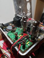
cool looking build!
As far as the voltage on the driver tubes, george has said in the past that the voltage doesnt need to be exact. On r36, im also running a remote mounted resistor that is bolted to the chassis to help it disipate the heat it generates. Havent had any issues after lots of use.
As far as the voltage on the driver tubes, george has said in the past that the voltage doesnt need to be exact. On r36, im also running a remote mounted resistor that is bolted to the chassis to help it disipate the heat it generates. Havent had any issues after lots of use.
- Home
- More Vendors...
- Tubelab
- After a 14 year run, the TSE must DIE!