I have a drill press, and an assortment of hand tools, so I can do basic stuff but nothing fancy.
Looking forward to see your googie style amp.
Looking forward to see your googie style amp.
I notice there are some non-generic resisters in the BOM. Are there beneficial sonic characteristics to the Vishay and Dale resisters? Or is it more a matter of size & easier to match? I know they're not expensive but I have a pile of stuff lying around so just wondering. . .
None of the resistors were chosen based on any real or perceived sonic qualities. You can use anything you have or prefer as long as it fits in the board, and meets the resistance, power dissipation and voltage rating requirements.
R6 and R36 should be at least 5 watt parts. R36 should be a 6 or 7 watt part if your B+ will be in the 400 volt range, it is now the hottest part on the board.
The B+ bleeder resistor R30 has the full B+ voltage across it.....it should be rated for that much or more.
I did choose metal film resistors in the audio signal path due to their lower in circuit noise. This is especially important when the resistance value is high and the signal level is low, as with R8 and R19.
The grid stoppers on the input tubes R31 and R32 should be carbon composition resistors. The actual value isn't too important, anything from 4.7K to 10 K is fine. There are people who will argue that a carbon comp is not needed, but I have seen some 5842's that require a carbon comp to keep them from oscillating.
R5 only dissipates a few milliwatts in normal operation, but eats a huge surge at turn on. Some cheap resistors have been known to fry.
None of the resistors were chosen based on any real or perceived sonic qualities. You can use anything you have or prefer as long as it fits in the board, and meets the resistance, power dissipation and voltage rating requirements.
R6 and R36 should be at least 5 watt parts. R36 should be a 6 or 7 watt part if your B+ will be in the 400 volt range, it is now the hottest part on the board.
The B+ bleeder resistor R30 has the full B+ voltage across it.....it should be rated for that much or more.
I did choose metal film resistors in the audio signal path due to their lower in circuit noise. This is especially important when the resistance value is high and the signal level is low, as with R8 and R19.
The grid stoppers on the input tubes R31 and R32 should be carbon composition resistors. The actual value isn't too important, anything from 4.7K to 10 K is fine. There are people who will argue that a carbon comp is not needed, but I have seen some 5842's that require a carbon comp to keep them from oscillating.
R5 only dissipates a few milliwatts in normal operation, but eats a huge surge at turn on. Some cheap resistors have been known to fry.
Such a detailed response, much appreciated!
R5 only dissipates a few milliwatts in normal operation, but eats a huge surge at turn on. Some cheap resistors have been known to fry.
It will indeed. Even with part that is specified in the BOM. A puff of smoke and a few sparks was what I got when I first switched it on to start the checkout. I have got a 2W replacement coming - my line voltages are always very high, so with a Hammond 372HX transformer and next to no load there was probably well over 330V going into the negative bias circuit.
Is there an easy way of slowing down the HT on the transformer so that doesn't put out quite such a spike at startup?
The reason for R5 is to lower the peak currents seen in the negative bias circuit. Without the resistor the diodes only conduct for less than a millisecond at the very peak of the AC voltage cycle. Even with fast diodes this can generate noise bursts on the HV winding that work their was back through the power transformer and get into the audio.
The usual way to blunt the current spike on power up is to wire an inrush current limiter device in series with the AC line to the power transformer input. These are essentially NTC thermistors that have a high (10's of ohms) resistance when cold that drops to under an ohm when they get warm. I use the CL-90 device on the USA 120 volt AC line, but a smaller (lower current) device would be used in the UK.
One can always add a CL-140 in series with the HV CT wire on the power transformer to blunt the spike in the HV winding itself. I have both on my SSE amps, but they run at much higher power and voltage than the TSE. The Inrush Current Limiters help protect some of today's less than stellar rectifier tubes.
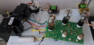
I am using the same Hammond 372HX transformer in my test amp as you and have not seen an issue with my board despite cranking my line voltage into the 140 vvolt range with a Variac.
Did your board blow the resistor specified in the parts list? It is specified for high current pulses, but I have only tested ONE of them, my earlier boards used some old 2 watt resistors that are no longer made.
The usual way to blunt the current spike on power up is to wire an inrush current limiter device in series with the AC line to the power transformer input. These are essentially NTC thermistors that have a high (10's of ohms) resistance when cold that drops to under an ohm when they get warm. I use the CL-90 device on the USA 120 volt AC line, but a smaller (lower current) device would be used in the UK.
One can always add a CL-140 in series with the HV CT wire on the power transformer to blunt the spike in the HV winding itself. I have both on my SSE amps, but they run at much higher power and voltage than the TSE. The Inrush Current Limiters help protect some of today's less than stellar rectifier tubes.
I am using the same Hammond 372HX transformer in my test amp as you and have not seen an issue with my board despite cranking my line voltage into the 140 vvolt range with a Variac.
Did your board blow the resistor specified in the parts list? It is specified for high current pulses, but I have only tested ONE of them, my earlier boards used some old 2 watt resistors that are no longer made.

I am currently out of TSE-II boards......Best guess is ship out to me on Friday.
Theyr'e here.....LOTS of them.
Now it's my turn to build some amps.....
In a thread about power supplies I mentioned my 845SE amp that I built 15 years ago with the second prototype TSE board. Unlike my Lexan TSE, I never swapped out that board. Pictures are in post #7 of that thread.
As I stated in post #12, the amp saw little use in my small room in Florida because it pumped over 500 watts worth of heat into the room. Now that I live in a place with a real winter, it should be welcome, but when I tried to awaken it from a several year sleep, it simply blew it's fuse and went back to sleep. I have waffled back and forth over whether to fix it, or do a total rebuild. It has places where 1100 volts of B+ is exposed, and I now have nosy grandkids, so it sits in it's corner, lonely and unloved........I guess its rebuild time and I think it needs a shiny new TSE-II board.
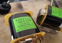
Industrial (step-down) control transformers used in reverse?
Attachments

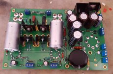
My board is completed and almost ready for final connections 🙂
Have a few follow ups:
1) What are PAD1/3/4 used for? I haven't seen anything in this thread or elsewhere, but they are connected in George's example on post #245
2) Where should the motor run cap be physically connected to ?
3) Why are there 3 connections for the L/R inputs? Which should be used?
Have a few follow ups:
1) What are PAD1/3/4 used for? I haven't seen anything in this thread or elsewhere, but they are connected in George's example on post #245
2) Where should the motor run cap be physically connected to ?
3) Why are there 3 connections for the L/R inputs? Which should be used?
Did your board blow the resistor specified in the parts list? It is specified for high current pulses, but I have only tested ONE of them, my earlier boards used some old 2 watt resistors that are no longer made.
I had the specified part - I was probably just unlucky and had an out of spec one. I have a 3W resistor in there now, and with no other changes the board is now sat there warming up nicely with a rock steady 380V and 65mA on a pair of cheap Chinese 300B's
My board is completed and almost ready for final connections 🙂
Have a few follow ups:
1) What are PAD1/3/4 used for? I haven't seen anything in this thread or elsewhere, but they are connected in George's example on post #245
2) Where should the motor run cap be physically connected to ?
3) Why are there 3 connections for the L/R inputs? Which should be used?
There is lots of information relating to the earlier version of the board here: Assembly Manual | Tubelab
I believe the part numbers are the same as on the original version of the TSE board.
Lots to read. Enjoy
2) Where should the motor run cap be physically connected to ?
One lead goes to a terminal in the T1-RED_YEL connector, and the other lead goes to the terminal in the CHOKE connector closest to the T1-RED_YEL connector. If using a choke and a cap, you may need to put two wires in one hole in the connector, or connect the wires together off board.
A true motor run cap should have no polarity. If you are using a polarized cap the negative lead goes in the T1-RED_YEL connector.
3) Why are there 3 connections for the L/R inputs? Which should be used?
The main reason was to make it easier for me to test the board. I made some little boards that have pins that fit these connections, a volume pot, and some input connectors.
The 4 connections closest to each other are all ground. Any of these can be used for the shield (ground) side of the input cable. The left most L-INPUT terminal is the hot terminal and should be used for the center conductor of the input cable. Likewise the right most pin on the R-INPUT connector is hot.
Wires that carry current especially the ground lead of the aux cap should NOT be connected to the 4 ground pins as this might cause hum.
Thanks so much George, so detailed and helpful.
I've been gathering the wiring information for the TSE from this and other threads. I have it all in a table if that is useful for anyone until the official guide is out.
George, for confirmation, it seems like there are quite a few wires that should be connected to T1-RED_YEL.
Is it a valid solution to have a single screw on the chassis, that the following are connected to:
1) T1-RED_YEL
2) AC Inlet (E)
3) Speaker/HP cold
4) PT grey EMI shield (I don't have this on my 370EX but it exists on other 300 series PT's)
5) Motor run cap (instead of directly to the T1-RED_YEL terminal)
Finally, the PT and OPT's sit directly on the chassis/top panel, but don't necessarily have continuity due to paint. Due people typical sand off the paint from the bottom of the bells?
I would say yes and yes. A single star ground point on the chassis is a good idea as well as scraping some paint from the spot where you bolt down the PY and OT. Maybe use a star washer for good measure
Don't know about others, but I used a wire brush attachment for my drill. I used it to remove paint so I could run a ground wire to the tx housings. If the housing is visible, then I removed the paint from the bottom of the feet, so you can't see the bare metal spots when tx is installed.
Otherwise paint is an insulator, and I can't see how you would get a good ground.
Otherwise paint is an insulator, and I can't see how you would get a good ground.
Thanks so much George, so detailed and helpful.
George, for confirmation, it seems like there are quite a few wires that should be connected to T1-RED_YEL.
Is it a valid solution to have a single screw on the chassis, that the following are connected to:
1) T1-RED_YEL
2) AC Inlet (E)
3) Speaker/HP cold
4) PT grey EMI shield (I don't have this on my 370EX but it exists on other 300 series PT's)
5) Motor run cap (instead of directly to the T1-RED_YEL terminal)
I only have the motor run cap (it was parallel connected to c5 directly before), T1-RED_YEL and AC Inlet (E) connected to the board.
The shield for the input wires connects directly to the AC Inlet earth, via a chassis star earth, and so do the OPT speaker output negatives. This saves some space.
Please share the table you made, and thanks.
Last edited:
As a minor housekeeping issue, is there any way to add the board graphics in Post 162 to the list of documents in Post 1? I ask because I needed a copy earlier today, but had forgotten which post it was in. Having all the docs in one place might prevent some frustration for future builders.
My amp has been dismantled for the past several days while I complete the chassis. So far it's been a challenge (the top plate alone has 197 holes, most of those for cooling), but it's coming together nicely.
My amp has been dismantled for the past several days while I complete the chassis. So far it's been a challenge (the top plate alone has 197 holes, most of those for cooling), but it's coming together nicely.
My amp has been dismantled for the past several days while I complete the chassis. So far it's been a challenge (the top plate alone has 197 holes, most of those for cooling), but it's coming together nicely.
When I put together my DG300B, I found a good way to drill a pattern of many holes: Perf plate! I used a piece of perforated aluminum sheet as a drill guide. I marked two holes in the pattern, drilled those, and held the perf plate in place with a pair of brass pins. Drill rod would work too. Naturally, this requires the holes in the perf plate to be the same (or smaller, I suppose) diameter as the desired ventilation holes in the chassis.
Tom
- Home
- More Vendors...
- Tubelab
- After a 14 year run, the TSE must DIE!