IIRC you're using 45s, correct?
The 3.3 uF cap should be fine as long as it doesn't increase the ripple appreciably. The 10H choke should help in that regard.
I'm facing a similar dilemma running 2A3s. My B+ voltage measures ~320 using a Hammond 270HX, 159S choke (4H, 65 ohms - it's what I had on hand) and the stock 47 uF 1st filter cap. This isn't a real issue with the Chinese 2A3s I'm using as test subjects, but is a bit high for NOS 2A3S and 45s.
I'll probably wind up dropping the value of C4 myself. I've done this many times on other projects, but only as part of a series of measured, incremental changes. I may well also swap out the choke; Hammond has a 7H model with a form factor identical to the 4H model I'm currently using, and with a higher DC resistance to boot (100 ohms). I don't expect the amp to be any quieter in any practical sense - it's dead silent as it is - but it certainly can't hurt.
Last edited:
IIRC you're using 45s, correct?
The 3.3 uF cap should be fine as long as it doesn't increase the ripple appreciably. The 10H choke should help in that regard.
I'm facing a similar dilemma running 2A3s. My B+ voltage measures ~320 using a Hammond 270HX, 159S choke (4H, 65 ohms - it's what I had on hand) and the stock 47 uF 1st filter cap. This isn't a real issue with the Chinese 2A3s I'm using as test subjects, but is a bit high for NOS 2A3S and 45s.
Thanks evanc and Mr_Zenith.
Yes, I'm using 45's.
How is my voltage higher than yours, if I've already reduced C4 and using a higher resistance choke? (Is it because the 2A3 draw more power?)
If I plug in 3.3uF, the estimation is 115mV ripple vs 85mV with the 4.7uF.
Although, PSUD also estimated that B+ would be 310 and not 330... I must have some parameters wrong.
Attachments
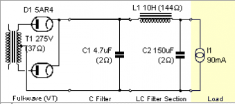
A 330 Ω resistor in series with the inductor would do the trick as well. I'd use a 10 W or 25 W chassis-mounted type as it'll burn about 3 W.
Tom
Tom
Quite likely. Increasing the current drawn by the output tubes will measurably lower the B+ voltage. I've been running the sino 2A3s at 50 mA, but I've also run 45s at 30 mA. My B+ was definitely higher with the 45s due to the lower overall current draw. I can't recall the exact voltages though.
Just noticed Tom's post. Good advice. I love those chassis mount resistors; they're easy to install and they dissipate well. 🙂
Just noticed Tom's post. Good advice. I love those chassis mount resistors; they're easy to install and they dissipate well. 🙂
A 330 Ω resistor in series with the inductor would do the trick as well. I'd use a 10 W or 25 W chassis-mounted type as it'll burn about 3 W.
Tom
Thanks Tom!
I had a 300Ω 10W Wirewound intended for dummy load and tried that out.
After biasing 45's to 27mA B+ measured 305V, which means the 45's are getting a bit less than 300V which is great.
For educational purposes, does it matter if the resistor is before or after the inductor? I have it right now going into the Choke connector closer to T1_YEL_RED which to my understanding means its coming after the inductor.
For educational purposes, does it matter if the resistor is before or after the inductor?
The principle of superposition: Z1 + Z2 = Z2 + Z1. In your case, Z1 = R and Z2 = 2pi*f*L. R + 2pi*f*L = 2pi*f*L + R. Thus, it does not matter if the resistor is before or after the inductor in the series combination.
On as my honours supervisor put it: "The electrons don't know which end of the wire they're in".
I would mount the resistor on the chassis and just run a wire from it to the inductor. Then take the other end of the resistor and the other wire from the inductor and connect them to the inductor connector on the board.
Tom
There a good chance your house Voltage is higher then expected. I used a 2.2uf for c4 and my previous version tse is silent as in no hum.
my Hammond power transformer has primary taps for 115 and 125 vac. This helps with high primary voltage coming from the wall
my Hammond power transformer has primary taps for 115 and 125 vac. This helps with high primary voltage coming from the wall
Thanks for the additional info Tom.
evanc, the Fluke shows ~122VAC at the outlet.
The Hammond 370EX I'm using has taps for 100,110,120VAC.. I am using the 120.
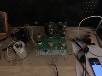
The mocked up TSE-II is playing pretty sweet music through my HD650.
There are a few open issues I will be exploring, sharing here in case this information is useful:
1) There is some small amount of hum when no music is playing. Initially, I measured around 8mV AC on the OPT. As an experiment, I changed the PS to CLCRC, using the 60uF motor RUN as the second cap, and adding a 300R resistor. Simulation showed this should bring ripple down, and indeed I was measuring 1mV AC after that. This reduced the hum but it was still audible. (I tried this with shorted inputs to eliminate any pot/input related issues) I think this is due to the headphone application- 5K:32 OPT's and sensitive high impedance cans. I highly suspect that this would silent with speakers and 5K:8 OPT's. Next, I will experiment with either CLCLC (as randytsuch tried) or a HV B+ regulator.
2) Loading resistors. Without any resistors, there is plenty of volume on the 300ohm HD650 with pot midway. Although, this puts a reflected load of 46K on the 45's.. Based on previous discussions, there was not a clear answer on whether this is a problem or not. The experiment shows the power is sufficient.. but does this cause frequency roll-off or distortion? I cannot know without proper testing tools. Anyhow, I experimented with a 100R resistor in parallel. Volume range is about the same (hard to tell in mockup), but I _think_ the sound was improved.. better clarity overall. I'll have to continue experimenting in my real setup with a proper source.
3) Power transformer buzz. I'm using the Hammond 370EX. People mentioned they did not get buzz from the 300 series. The buzz I hear is audible only when putting the ear very close, less than half a foot. Is this expected, or are the Edcor / Custom PT completely silent ? The 370EX has 144mA, maybe it is over-utilized ? I read somewhere that you want only about 70% of the PT loaded to avoid noise.
On Tubelab website it is mentioned:
> The 45 should be biased in the 25 to 30 mA range. I use 28 to 30 mA on 280 volts, and 26 or 27mA if operated at 320 volts.
Based on the RCA data sheet, at 275V it should be 36mA (or am I understanding this wrong?)
If this is the case, any reason to prefer 30mA over 36mA in 275-280V range?
evanc, the Fluke shows ~122VAC at the outlet.
The Hammond 370EX I'm using has taps for 100,110,120VAC.. I am using the 120.
The mocked up TSE-II is playing pretty sweet music through my HD650.
There are a few open issues I will be exploring, sharing here in case this information is useful:
1) There is some small amount of hum when no music is playing. Initially, I measured around 8mV AC on the OPT. As an experiment, I changed the PS to CLCRC, using the 60uF motor RUN as the second cap, and adding a 300R resistor. Simulation showed this should bring ripple down, and indeed I was measuring 1mV AC after that. This reduced the hum but it was still audible. (I tried this with shorted inputs to eliminate any pot/input related issues) I think this is due to the headphone application- 5K:32 OPT's and sensitive high impedance cans. I highly suspect that this would silent with speakers and 5K:8 OPT's. Next, I will experiment with either CLCLC (as randytsuch tried) or a HV B+ regulator.
2) Loading resistors. Without any resistors, there is plenty of volume on the 300ohm HD650 with pot midway. Although, this puts a reflected load of 46K on the 45's.. Based on previous discussions, there was not a clear answer on whether this is a problem or not. The experiment shows the power is sufficient.. but does this cause frequency roll-off or distortion? I cannot know without proper testing tools. Anyhow, I experimented with a 100R resistor in parallel. Volume range is about the same (hard to tell in mockup), but I _think_ the sound was improved.. better clarity overall. I'll have to continue experimenting in my real setup with a proper source.
3) Power transformer buzz. I'm using the Hammond 370EX. People mentioned they did not get buzz from the 300 series. The buzz I hear is audible only when putting the ear very close, less than half a foot. Is this expected, or are the Edcor / Custom PT completely silent ? The 370EX has 144mA, maybe it is over-utilized ? I read somewhere that you want only about 70% of the PT loaded to avoid noise.
On Tubelab website it is mentioned:
> The 45 should be biased in the 25 to 30 mA range. I use 28 to 30 mA on 280 volts, and 26 or 27mA if operated at 320 volts.
Based on the RCA data sheet, at 275V it should be 36mA (or am I understanding this wrong?)
If this is the case, any reason to prefer 30mA over 36mA in 275-280V range?
Attachments
Surplus Parts for TSE - including original version specific
I have parts accumulated for the original TSE that I will never complete now. I gathered most of them years ago so there a number of now obsolete parts that came from reputable sources when they still carried them. Would anyone be interested in:
I have parts accumulated for the original TSE that I will never complete now. I gathered most of them years ago so there a number of now obsolete parts that came from reputable sources when they still carried them. Would anyone be interested in:
- 16 x 2SK2700 (yes, lots!)
- 23 x NDF02N60ZH (even more...)
- 2 x PQ5EV5
- 3 x the double heatsinks (=one set)
- Snap in 450v caps - 100uF, 150uF, 220uF and 470uF
- A bunch of different values for R14/R25
Last edited:
On Tubelab website it is mentioned: > The 45 should be biased in the 25 to 30 mA range. I use 28 to 30 mA on 280 volts, and 26 or 27mA if operated at 320 volts.
Based on the RCA data sheet, at 275V it should be 36mA (or am I understanding this wrong?)
If this is the case, any reason to prefer 30mA over 36mA in 275-280V range?
Based on the silence of this, I will proceed with 30mA at 275V.. unless there is a compelling reason to use 36mA.
Besides that, I was curious which types people have tried in the TSE and whether any difference was observed between types (i.e, PP, Film & Foil etc)? The most relevant information I found was these quotes by George: > In this design the coupling caps work into an almost purely resistive load. This makes the coupling capacitors far less critical than they are in a conventional amplifier design. It is still an important capacitor and a low quality capacitor will still have a detrimental effect on the sound > I have not tried any Teflon caps, but some builders report good results.
Clarification: (unfortunately the editing window has expired) In the above post, I meant "which types _of coupling caps_ people have ..." Also, I don't mean to start a holy war on the topic, just some concise recommendations and impressions would be helpful
Clarification: (unfortunately the editing window has expired) In the above post, I meant "which types _of coupling caps_ people have ..." Also, I don't mean to start a holy war on the topic, just some concise recommendations and impressions would be helpful
I use high quality Russia telfon in my tse II and and in others, and am extremely pleased with the result in my TSE II. I also like and have used Mundorf silver gold oils in another amp but to expensive to use everywhere, especially when the excellent Russian teflons are so much cheaper and very little difference.
I used Jensen aluminum foil / paper & oil in a push-pull KT88 amplifier and love the sound (hooked me on tube gear). I too, have subsequently acquired a stockpile of Russian Teflon caps but in my TSE build will use a pair of leftover Mundorf silver/gold & oil that never met their intended use. I have since “came to my senses” regarding capacitors (my stockpile is from many moons ago) and wouldn’t spend the money on them that I have in the past, though they do actually serve a purpose: to impress those who like fancy things for their own sake.
I think some people do use these to impress, but in addition, they are also extremely good caps as well, and if someone has money to burn, why not. Having said that, I wouldn't buy the Mundorfs again. If one is patient, these Mundorf can be got for a significant discount, such as I managed to get mine for. They were still much much more expensive than the Russian k72-11s that I bought as a matched pair at 15usd each. The big disadvantage of teflons are is that they are significantly larger than Mundorfs or most other caps, but I have the space.I wouldn’t spend the money on them [Mundorf silver gold oil] that I have in the past, though they do actually serve a purpose: to impress those who like fancy things for their own sake.
These k72s in my TSE II sound just as good if not better than the Mundorf silver gold oil in my other amp. This difference could though be due to the excellent design of the TSE, as I've not compared them both in the TSE itself.
Both, to my ears, give a very high level of transparency, air, clarity and naturalism.
Last edited:
Thanks both for your comments on caps.
Need some help resolving a noise issue I'm having with the TSE.
After first build, there was an audible hum through my headphones. The headphones are 103db/1V and with the 5K:32 opt's, it seems like the default CLC filter does not eliminate hum entirely.
I've experimented with the 21st Century Maida Regulator in place of the CLC filtering (this should eliminate ripple almost entirely), and while the hum seems to be gone, there is a noise that I can't figure out the source of. It sounds a bit different than the hum I had earlier, but can't quite characterize it.
My current suspicion is either an issue with the layout while mocked and/or grounding.
Are there any measurements I can make with a DMM (Fluke 87-V) to try and find the root case? I measured AC at the headphone out and it measures 0.3mV, but I question the accuracy of that measurement.
I'm also setting up Pete Millet's audio interface to start measuring with ARTA/AudioTester... are there any tests I can run that would help find the issue?
... I've experimented with the 21st Century Maida Regulator in place of the CLC filtering (this should eliminate ripple almost entirely), and while the hum seems to be gone, there is a noise that I can't figure out the source of. It sounds a bit different than the hum I had earlier, but can't quite characterize it. ...
The 5842/417A is a high gain VHF tube, and can oscillate under some circumstances. Oscillation can "sound" a lot of different ways depending on the frequency / mode of oscillation. Sometimes there is no "sound", just erratic or unexpected operation.
You could try pulling the 5842's and see if whatever you are hearing in your headphones, changes, or disappears.
Pulling the front end tubes probably won't make any change in what you are hearing, but you might as well eliminate it as a possible cause before proceeding further.
IMPORTANT BOM CHANGE
......................IMPORTANT BOM CHANGE......................
Two builders have seen their boards fail due to R5 going open. This will cause the negative bias to disappear letting too much current flow in the output tubes.
The part used in the original TSE worked fine, but was obsolete, not stocked at Mouser of Digikey.
The Mouser part number for R5 was chosen based on manufacturer data stating it's capability to withstand a pulse of over 100 watts for 10 mS. Two out of two parts have worked fine in my boards, so I put that part number in the BOM. These two failures have proved that the tiny little part is NOT capable od eating the surge current needed to charge C6 on power up. This current is dependent on the internal resistance of the power transformer's windings and is vrey much transformer dependent, but I do NOT recommend using this part and it has been removed from the BOM.
I got several resistors from Digikey yesterday and more on the way from Mouser, so I will be blowing up some resistors in the near future. The BOM will be updated as soon as I have the numbers for a reliable part.
In the mean time I would recommend removing the Vishay part numbered PR01000102700JR500 from your board if it is installed. The safest bet for a replacement is a wirewound or metal oxide part good for at least 2 watts.
See this thread for some more info:
https://www.diyaudio.com/forums/tubelab/340628-tseii.html#post5863848
- Home
- More Vendors...
- Tubelab
- After a 14 year run, the TSE must DIE!