
Well, I went with the Softone OPT. I admit it, I'm a sucker for R-core. Price is still very good although shipping from Japan isn't cheap.
You won’t be disappointed.
Is 200 mA a reasonable constant current to use when simulating the power supply? I noticed George used it as an example earlier. If I use 300b's at 65 to 70 mA and 370V B+ I guess that means 130 to 140 mA for the power tubes. Does 60 to 70 mA represent the current used by the rest of the amp?
Speaking of power tubes. It's recommended not to use expensive tubes until everything is confirmed as working correctly. Being new to power tubes, I don't have any old 300b's lying around. What do you guys do when it comes time to test the amp?
Speaking of power tubes. It's recommended not to use expensive tubes until everything is confirmed as working correctly. Being new to power tubes, I don't have any old 300b's lying around. What do you guys do when it comes time to test the amp?
I think it is hard to do this hobby and not have a variac. It is such a comfort to slowly ramp up the voltage and make measurements around the circuit and check that there is nothing untoward going on. They are always available second hand, and you can generally sell it for what you paid for it.Speaking of power tubes. It's recommended not to use expensive tubes until everything is confirmed as working correctly. Being new to power tubes, I don't have any old 300b's lying around. What do you guys do when it comes time to test the amp?
Thank you @Old Hector. Happily, I have a Variac and the slow Variac approach would give me confidence. Seems like I had to remember that because the Variac was hiding, unused in the basement.
I've been playing with PSUD2 today. Do you guys find that it gives you accurate simulation? The reason I'm asking is that several people are successfully using smaller PT than PSUD2 says would meet my targets. It would require them to use lower bias current and/or B+. I'm targeting about 375V B+ and 70 to 80 mA using a 5k OT. If the 300b bias is set at 75 mA and the 5842 is at nominal 25 mA, then it would seem that B+ needs to run at least 200 mA and probably more. PSUD2 suggests that I would need 700VCT and about 400 mA to meet those targets even with a low resistance choke. At this point I think I believe PSUD2 and that some people have gotten a good sounding amp with lower B+ and bias but I would like a touch more confidence before buying a transformer and choke.
Thoughts?
Are these numbers ok for 300b:
b+ 380v; b- -235v; mosfet 160v; 5842 plate 175v;300b 75mA?
I have a Maida regulator on the b+ and that is fed by 410v coming from the rectifier.
To get the 5842 filament voltage up to 6.3v I had to jumper R3.
The amp sounds weaker than I would expect, and quite muffled(both channels). Any ideas what I might have done wrong?
Henry
Last edited:
@tubelab - What is the sensitivity of the design to the input impedance resistors, R8, R19? What do you expect would change if the value of these resistors is reduced.
As background, my current preamp has only balanced out connections. I have a pair of CineMag 1:1 input transformers that I could use to convert balanced to single end at the input of the TSE-2. The trouble is the transformer wants something like 15k loading it's secondary and as I'm sure you know, transformers are picky prima donnas. I could put a 15k resistor across the secondaries and parallel it with 100k or 121k at the input of the TSE-2, but I don't understand the effect on the TSE-2.
My other alternatives are to root around in the pre-amp and try to pick up a single ended signal or leave the vinyl chain out of the picture and only use digital path because it has both single ended and volume control. This second approach may be the first step, just so I can get a sense of the amp.
Thanks in advance.
Jac
I do, as long as I am very careful about getting it all configured properly, especially the transformer properties and the load.I've been playing with PSUD2 today. Do you guys find that it gives you accurate simulation?
Thanks for the advice. I seem to remember that the B- was about -160 on a previous build so I might try to raise that first. If that doesn’t help then I’ll take the Maida out. I have an old oscilloscope so I will take a look at the stability.@Henry - I'm no expert but those numbers look too high to me. Is there any chance to use the standard regulator approach instead of the Maida, just to know if the source is the Maida or the bare transformer being too hot?
I have run into a lot of issues over the years, but I have never had this fuzzy output. It sounds like it could be due to a poor soldering job, so I’ll check it over.
That resistor is there only to provide a path from grid to ground for the 5842 tube. The 5842 spec is 300K maximum. The minimum is governed by what your source can drive. It there is continuity from grid to ground through the transformer coil the resistor can even be left out. If the transformer wants 15K, there is no problem with using a 15K resistor for R8 and R19. If you don't want to mess with the amp, put whatever you need in parallel externally.@tubelab - What is the sensitivity of the design to the input impedance resistors, R8, R19? What do you expect would change if the value of these resistors is reduced.
That's great news! Thank you very much. I don't know whether balanced transformer input or single ended input will sound better or worse but at least I will be able to experiment without breaking the amp.
Hi all,
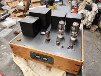
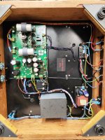
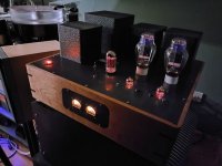
I finally finished my build. I cheated somewhat here since I bought a populated board from another member here, I just had to add some of my own preferences for coupling caps etc.
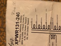
I went with cable lacing for the looms just because I thought it would fit nicely with the valve era. Power transformer is a custom toroid, output transformers are a somewhat unusual 5k:6R set donated from a damaged amp that I repaired for a friend. Everything else is pretty much standard. Since those photos were taken I added test points on the top plate for the 5842 valves. I fitted a 1V scale meter and switch for checking the 300b current. I 3d printed tubes that guide a screwdriver down to the adjustment pots so that you can't short anything when adjusting, and printed covers for the 2mm sockets I used for test points. Same deal for the big polypropylene caps for power supply.
Sound is really good, very happy with how it sounds - I had it running on a board before making the chassis so I knew it was worth the effort.
Thanks to George for the design and making boards available and to all who gave the advice in the thread here.
I finally finished my build. I cheated somewhat here since I bought a populated board from another member here, I just had to add some of my own preferences for coupling caps etc.
I went with cable lacing for the looms just because I thought it would fit nicely with the valve era. Power transformer is a custom toroid, output transformers are a somewhat unusual 5k:6R set donated from a damaged amp that I repaired for a friend. Everything else is pretty much standard. Since those photos were taken I added test points on the top plate for the 5842 valves. I fitted a 1V scale meter and switch for checking the 300b current. I 3d printed tubes that guide a screwdriver down to the adjustment pots so that you can't short anything when adjusting, and printed covers for the 2mm sockets I used for test points. Same deal for the big polypropylene caps for power supply.
Sound is really good, very happy with how it sounds - I had it running on a board before making the chassis so I knew it was worth the effort.
Thanks to George for the design and making boards available and to all who gave the advice in the thread here.
Attachments
I removed the Maida regulator and put in R4, but I still get a muffled weak output. I tried swapping out the OPTs and valves with no improvement. Is it worth trying to bring B- up? It is -256v. The mosfets have +156v, -83 and -96v. Could that be the problem?
Attachments
I went over the contacts with my soldering iron a second time and it seems like it was a loose contact. It sounds much stronger and clearer. It is still not perfect (the bass is a bit boomy), but it has cheap 300bs in it, and r4(I will swap in the Maida). It still would be reassuring to know whether -250v is okay for the bias if someone knows.
First of all, I apologize in advance for suggesting things that you have already tried 12 times. That said, it does seem like something is wrong. This is the way I'm understanding it. Please, someone correct me if I have this wrong.
Assuming R5, R6, R11, R12, and R13 are the correct values, there is no direct way to adjust B-. The way that B- is adjusted is by adjusting the wiper on R12 which, through Q1, changes the amount of current drawn through the output tubes. I believe that B+ gets larger as B- gets smaller. Since your B+ and bias current were already good enough, you may have to lower B+with resistance in the choke circuit to get B- closer to the suggested -184V.
I wish someone with knowledge would chime in and suggest an acceptable B- range for 300b tubes. From what I have read there are few specs for B- in the datasheets. The closest I came was New Sensor 300b where they state that the limiting value of grid voltage (to ground?) is -220V. Maybe you should try to measure grid voltage. I'm guessing that it will be closer to -60 than -220. If it really is much more negative than -60 then it really could be affecting the way it sounds because it's way off the curves for any datasheet that I've seen.
In the end, when none of this helps, I would probably go back to the Tubelab/Design/Tubelab SE/Assembly Manual and follow both the "Check out" and Bias Settings" pages to the letter (except for R7 which isn't there anymore). Oh yeah, and check the continuity and values of R5, R6, R36, R11, R12, and R13 for the millionth time.
Good luck and learn a lot because I may be asking you for help soon.
Jac
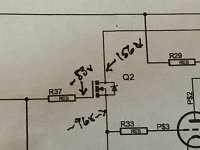
Thanks Jac! The 250v that I was referring to is the “negative B- supply” on George’s schematic. I think the Tse website says -150v, but it will vary with the PT. The Q2 mosfet sheet says 450v max so it must be heavy duty, so I am guessing the 260v across them is probably ok. The B- voltage is set by r5/c6/r6/c7 (rcrc filter). I am guessing I could also use the other winding on my PT: I am using the 660v winding which gives 400v once smoothed out (which is just right for the B+). Perhaps I could use the other winding (taps) 520v to feed the B-?
Attachments
Last edited:
The amp sounds good at mid to high frequencies but base is distorted. Perhaps my speakers aren’t used to so much bass?
Just my opinion, but before I considered switching to the 420V tap, I would check grid to ground voltage was in the -61V to -74V range. If it was then maybe -250V for B- is OK. If it's not, then I would consider adding a couple Ohms of series resistance to the choke (or R4) and reset the bias. Because B+ and B- (plus I assume grid voltage) move in opposite directions with bias adjustment, the hope is that you could find a more balanced operating point without giving up so much B+ voltage. After all, the 420 Volt tap is only capable of about 300V B+.
Last edited:
- Home
- More Vendors...
- Tubelab
- After a 14 year run, the TSE must DIE!