Thanks for the advice. The 300b reg is at 6.3, the other stuff I will try to check on Sunday. To use a radio to sniff out oscillations: does it matter am/fm frequency?That sounds like a low level hum
Tune the radio to a weak analog AM station. Place it near the amp and fire the amp up and play some music. Use a non metallic instrument to move the wires leading to the 300B tubes. Anty interruption, buzzes or crackles that come from the radio could be from oscillation. Without changing anything cut power to the amp while still doing whatever disturbed the radio. If the disturbance stops, the amp is likely oscillating. I have created some circuits that could blank out a TV set that was connected to cable TV in another room. TV sweep tubes connected up with clip leads will do that!

My Lexan original TSE still has the original Raytheon 5842 tubes in it, and they were pulls when I got them. The amp got daily use powering the speakers on my PC when I built it. It was there for about 2 years, and has seen intermittent use since.How long do we think 5842's last in the TSE-2?
A lot depends on the tube, its original application and how it is currently used. Googling "5842 vacuum tube" brings up more BS than fact, especially the "used exclusively in Russian military radios" statement. The 5842 was designed expressly for use in high frequency telephone RF carrier repeater amplifiers, some of which were employed in underground or undersea applications were repair was rather difficult. Several manufacturers made this tube. I have seen Raytheon, Western Electric, Ericsson, Tung Sol, and a few others I can't remember. WE also called it the 417A with some tubes marked 5842 / 417A. Raytheon's were the most common flavor seen in the US, these tubes were made to last.I feel like I have always underestimated the typical longevity of tubes.
Look at the TV sweep tubes made in the last years of US tube manufacture, and how they were abused. Our old Sears branded Sanyo built color TV ate it's 6JS6 pretty regularly at one year intervals. I worked in a Philco authorized TV repair shop in high school doing in home repair on large console TV sets. We changed between 5 and 12 6LU8's a week! Philco ran those things right at the edge of red plate in their 25 inch consoles. They lived far longer in the 21 inch sets.
The vertical sweep tube (6LU8) in a TV is a class A SE amp optimized to work at one frequency 60 Hz in the US, and 50 Hz in other countries. Likewise, the output tube in our class A SE audio amps will need to be changed far more often than the driver tube. I recently sold the SSE I built about 15 years ago. it still had the original 12AT7 in it. I don't know how many output tubes it saw since I rolled them around a lot depending on what I was listening to and what speakers I was using.
Attachments

You have orders of magnitude more experience than I, George, but mine aligns mostly with yours on this. I have never burned out a driver tube. The only output tubes I have ever burned out were questionable Shuguang EL34 running in my first tube amp, which was a Chinese push-pull that initially ran the output tubes beyond spec. After some component and topology changes, I never burned out another tube in that amp.
Have never lost a tube in my SSE, and I’ve sometimes forgotten to turn it off overnight or longer. I feel pretty safe having ~10 driver tubes and 6 sets of output tubes for the SSE.
Having said all this, I always have my eye open for good deals on tubes, and I always get excited when I find some. I have to admit, part of the reason I am building a TSE-II is because I like hunting for tubes.
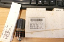
OK, why did a box containing 5 50L6 tubes, 10 50FE5's, 10 12AU6's and 10 12AW6's show up at my house today, and another pair of Ebay scored 50FE5's show up yesterday? No, they are not for old radios, or any old stuff. There is another box full of stuff that I fetched from the storage trailer destined for the same place. To me, the real question is what did the US military do with 50L6 tubes in 1987? That bar code is an FSN (Federal Stock Number).
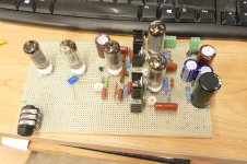
This old unfinished breadboard might provide a clue or two.
This old unfinished breadboard might provide a clue or two.
Attachments
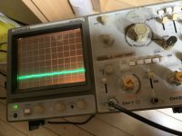
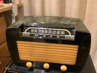
Hi George, I tried putting my 1940s radio by the TseII and I didn’t notice any change when turning on then off. The reception for am is not terrific in the uk. There is only one channel I can get is at 700kh and that is very weak. Is there any other way to check for oscillation?If you have a scope, look at the filament voltage on the 300B's. It should be ripple free DC.
I put my oscilloscope on the filament and the ripple is around 2.5 mV.
I had this board running fine with 45s but I decided to change to 300b because the 45s always sounded nice but weak with my system. Perhaps I could switch back to see if the 45s still sound ok?
Attachments
Update: I converted back to the 45s and have the same distortion problem. I must have damaged something in the transition to 300bs. Should I try replacing the mosfets?
Last edited:
Hi Henry,
Since nobody else is answering, I'll toss in a few thoughts. I don't know if it's even possible but could you move the output tubes to the pcb or at least close enough to use much shorter wires? Although the AM radio test seemed to indicate that it wasn't oscillation, I might want to completely eliminate that possibility. And it's something that might stay the same as you changed to the 45's. Other than that, I think your instinct is good to change the mosfets. You have checked all the resistors in the signal path and swapped out input tubes, output tubes, and OPT. What else could there be?
Since nobody else is answering, I'll toss in a few thoughts. I don't know if it's even possible but could you move the output tubes to the pcb or at least close enough to use much shorter wires? Although the AM radio test seemed to indicate that it wasn't oscillation, I might want to completely eliminate that possibility. And it's something that might stay the same as you changed to the 45's. Other than that, I think your instinct is good to change the mosfets. You have checked all the resistors in the signal path and swapped out input tubes, output tubes, and OPT. What else could there be?
Hi Henry,
Just wondering if you've had any electrical upgrades in or near your place while working on your amp. It may be totally unrelated, but for what it's worth, here’s my experience:
Years ago, I built the Hagerman Labs Cornet2 phono stage, and while it sounded nice, it also exhibited pretty noticeable hum. As it turned out, every other phono stage I've tried - both tube and SS - also had noticeable hum. I assumed this was an unavoidable evil of high gain, until one day I plugged it into a different outlet with no ground, and the hum became significantly lower. I can't explain this, as both outlets are on the same circuit. The "humming" outlet is the last one in the line and has a dedicated ground (a yard-long copper-plated rod buried in the ground), and all gear is plugged into an EMI/RFI filter. Both the SSE and Willsenton 300B amps produce no noticeable hum with open or CD input into 97dB speakers. And when I plugged this phono stage into my son's system at his house, it had almost no hum at all.
I also used to work from home and would listen to a local low-power FM station on a vintage Akai tuner. It worked fine until the day I replaced the fluorescent lights in my kitchen with LED tubes. From then on, whenever the kitchen lights are on, my FM tuner picks up so much hum that it's impossible to tune into any station.
Not sure it's relevant but I just ran across this on the powerelectronictips website.
"The high impedance of MOSFET inputs can lead to stability problems. Under certain conditions, high-voltage MOSFETs can oscillate at high frequencies because of stray inductance and capacitance in the surrounding circuit (frequencies usually in the low megahertz range). Device manufacturers recommend that a low-impedance gate-drive circuit be used to prevent stray signals from coupling to the MOSFET gate."
"The high impedance of MOSFET inputs can lead to stability problems. Under certain conditions, high-voltage MOSFETs can oscillate at high frequencies because of stray inductance and capacitance in the surrounding circuit (frequencies usually in the low megahertz range). Device manufacturers recommend that a low-impedance gate-drive circuit be used to prevent stray signals from coupling to the MOSFET gate."
Thanks, just waiting for the mosfet delivery. The reason I moved the 300b sockets off the board was because the sockets were so tight that I was bending the board every time I put in or out a valve. I have real trouble sourcing good sockets!Hi Henry,
Since nobody else is answering, I'll toss in a few thoughts. I don't know if it's even possible but could you move the output tubes to the pcb or at least close enough to use much shorter wires? Although the AM radio test seemed to indicate that it wasn't oscillation, I might want to completely eliminate that possibility. And it's something that might stay the same as you changed to the 45's. Other than that, I think your instinct is good to change the mosfets. You have checked all the resistors in the signal path and swapped out input tubes, output tubes, and OPT. What else could there be?
I have had similar experiences, but the distortion is not a hum. Something else. I also have a cornet, nice bit of kit.Hi Henry,
Just wondering if you've had any electrical upgrades in or near your place while working on your amp. It may be totally unrelated, but for what it's worth,
I am thinking that I must have damaged something, it was working fine before I switched it to 300b. Now it is back as a 45 set up so I am going to first try replacing the mosfet, and putting the valves back on the board…The high impedance of MOSFET inputs can lead to stability problems
I completely understand that concern. Having had that problem on a previous project I tried the more expensive, collet type socket (see link). I think that they are a little better but still very tight.The reason I moved the 300b sockets off the board was because the sockets were so tight that I was bending the board every time I put in or out a valve. I have real trouble sourcing good sockets!
Machined pin sockets
I'm thinking about cutting pieces of plastic to brace the pcb between the pcb and the base.
Hi lehmanhill,
I just received these - but they are really tight. I don't think I can fit my valves without breaking them.
https://www.hificollective.co.uk/valvebases/vtb4-st-belton-ux4-chassis-mount-valve-base-gold.html
I found some like the ones you suggest and will order those.
Please post pictures if you stabilize the board.
Thanks.
Henry
Hi Henry,
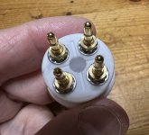
Regarding the machined pin sockets, I actually ordered the ceramic ones, not the bakelite ones I linked, but the sockets are the same. I just took another look at them since you were ordering some. I have an older set of 45's and they slide in and out with reasonable force. My 300b's are brand new Genelex PX300B are stiffer. If you look closely at the picture, the cuts inside the socket don't go full depth. If I push the 300b into the socket and leave 6 mm or so between the bottom of the valve and the top of the socket, then they are tight and have good connection. Push them in all the way and they are too tight.
One problem that will require some tweaking is soldering the pins to the pcb. The hole in the pcb is much larger than the pins. There are two approaches that I am considering. First is soldering the nuts on the pins to the pcb and maybe filling in the holes on the bottom a little. The other idea is to make a washer out of copper or brass that sits on the first shoulder of the pins. Then soldering the pin and washer to the pcb and each other. Both ideas seem possible but I haven't done it yet.
Attachments

Good news, I moved the sockets back onto the board as George suggested a the distortion is gone. I guess there was oscillation due to moving the sockets off the board. I am not sure why the radio test didn’t pick it up. It sound better then when I started so I seem to have fixed the other weak signal/distortion issue along the way. I am still worried that the sockets are too tight and am thinking of how to stabilise that area of the board - perhaps adding a post.
- Home
- More Vendors...
- Tubelab
- After a 14 year run, the TSE must DIE!