Thanks guys. I'm in a bind. If edcor were still shipping tobtge uk I'd just order the xowr 131 240 but that's no longer and option. The 373ex is enormous and aesthetically off putting. What other sensible options are there, 374bx?
Last edited:
The 374BX will put your B+ in the way over 400 volt range, probably well over 450 volts. This may be OK for a cathode (filament) biased 300B, but not the TSE-II which has the filament grounded on one end. Most 300B's want less than 400 volts across them.Thanks guys. I'm in a bind. If edcor were still shipping tobtge uk I'd just order the xowr 131 240 but that's no longer and option. The 373ex is enormous and aesthetically off putting. What other sensible options are there, 374bx?
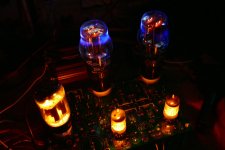
I have a TSE-II that uses a Hammond 372HX. B+ is about 375 volts depending on the line voltage which varies with the outdoor temperature. I can run 300B's in this amp, and I often run some cheap Chinese 2A3's in it. Yeah, 375 volts is way over spec for the 2A3, but these have eaten that much voltage for a few years. They put out a good deal of blue glow too!
Attachments
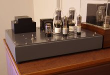
Thank you George, those 45's certainly look the part, makes me miss my old 88's.
I have a company here in the UK, quite nearby luckily who have quoted what I thought was a good price for a pt with 240v primary, ct 660v secondary @ 250ma, 5v @ 2a and 6.3v @ 4a and weighing in at 4.5kg.
If you were to size an ideal PT for a 300b tse2 would you go with the above or would you tweak it up anywhere?
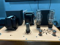
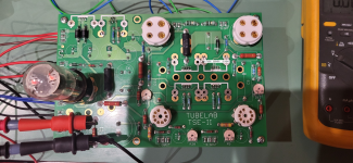
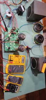
I've seen a lot of designs showing 6E5P driving the 300b. Thought I'd try it on the TSE-II instead of the 417A, with adapters wired in TRIODE. They took some time to run in but sound fantastic. Very dynamic sound on the Altec 604E (bass driver). Another option instead of the 417A I guess.
I just plugged them in, set the plate to 180v and its running about 3.6v /4.3v, about 10.9 and 13ma. The board has all the b.o.m parts.
Any comments on ideal operating points.
I just plugged them in, set the plate to 180v and its running about 3.6v /4.3v, about 10.9 and 13ma. The board has all the b.o.m parts.
Any comments on ideal operating points.
Attachments


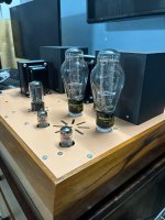

A very good idea! The 5842 is hard to find in Europe and expensive. Another candidate would be the EC86 or E86C.I've seen a lot of designs showing 6E5P driving the 300b. Thought I'd try it on the TSE-II instead of the 417A, with adapters wired in TRIODE. They took some time to run in but sound fantastic. Very dynamic sound on the Altec 604E (bass driver). Another option instead of the 417A I guess.
I just plugged them in, set the plate to 180v and its running about 3.6v /4.3v, about 10.9 and 13ma. The board has all the b.o.m parts.
Any comments on ideal operating points.
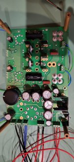
At first power on I notice some strange behavior. I have no B- at all, only 1,2VDC. Power off and double checking, what an idiot I am. Turned around IC1 and IC2, and Q1 andQ2. Desolder them and solder them in the correct orientation. (It's not an easy job, so burn my fingers.) Power on with a safety bulb B+ it is ok, but B is still missing. I have blown the IC1/2 360VDC on all 3 pins. Q1/2 has 220VDC on the middle pin and -5,7VDC on -2,2VDc on the right.
Need to order new parts. Are there any other parts to be checked?
Need to order new parts. Are there any other parts to be checked?
Attachments
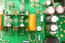
The usual suspect in the case of missing B- is R5, and sometimes R6. Make sure that C6 and C7 are installed correctly. The positive end goes to ground and the negative ends go to R6. If this fails to fix the problem post a picture of the other side of the board so I can look for errors. This side looks good.
When the mosfets and CCS chips are mounted on the bottom, they go on the back side of the heat sinks. See picture.
When the mosfets and CCS chips are mounted on the bottom, they go on the back side of the heat sinks. See picture.
Attachments
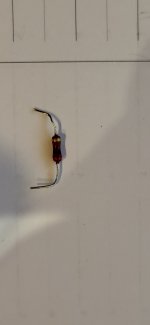
Ah, yes... the ol' R5. When mine blew 5 or 6 years back it nearly gave me fits because the damage was almost invisible. I replaced it by shoehorning a 5W cement resistor of equal value in the same space (yes, it can be done). It hasn't given me a bit of trouble since.
R5 must eat a short burst of current to charge the filter caps at turn on. The part specified in the original parts list was chosen specifically for its surge current rating. Unfortunately, they seem to be the most unreliable part of several different components that I have tried. The resistance value is not critical, anything from 240 ohms to 470 ohms will work. The resistance is there to reduce the noise created by the diodes as they switch on every half cycle.
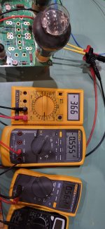
Replaced the R5 with a combination of 4 res to achieve 270V 5w. B- is now present, B+ ok. Set the left 5842 plate was set to 176 volts and the right 5842 plate is 176 volts. Set the R12 or R23 to the most negative voltage -22V. Connect the test speakers and insert the 300B. Power on and another problem. The meters across R18 and R29 show 1,5V, then a spark in the rectifier tube from the bottom to the top. shutting down.
Are my 300B bad/damaged? I bought them used, but the guy who sold them advertised them as a matched pair of tubes used for about 40-50 hours in like new condition with original packing.
Are my 300B bad/damaged? I bought them used, but the guy who sold them advertised them as a matched pair of tubes used for about 40-50 hours in like new condition with original packing.
If you are using 10R resistors and there is a drop if 1.5V across them, then the current must be 1.5/10 = 150mA. That would seem to be a bit extreme for a 300B. The data sheet says 60mA, so 60mA = V/10R, hence the expected voltage drop is circa 0.6V.
The excess current would put a strain on the rectifier. If the 300B is dissipating that much it implies the bias is not set correctly?
What voltage measurement do you get on the grid pin of the 300B without the tube in place? There are two variable resistors R12 and R23, did you adjust them so that bias was at the max negative value as part of the setup?
-22v is not enough... The 300b will try to pass way too much current. Hence the flashover in the rectifier tube. Check the bias supply, you should have between -50 to -90v or so available.Replaced the R5 with a combination of 4 res to achieve 270V 5w. B- is now present, B+ ok. Set the left 5842 plate was set to 176 volts and the right 5842 plate is 176 volts. Set the R12 or R23 to the most negative voltage -22V.
The R12 and R23 are set to max negative value that is in my case -22, i can ser them higher.
I am afraid that I smoked the tubes...
I will set the biassuply to -60 and will see.
I am afraid that I smoked the tubes...
I will set the biassuply to -60 and will see.
That’s a good idea, start with the bias supply around -60 V, and try again. Tubes are pretty resilient, they might be just fine. But without enough negative bias, they will try to push too much current through themselves, stressing the entire amp…. Especially the rectifier tube😱
Make sure to have meters hooked up on the 10 ohm resistors to monitor current through the output tubes as you do this. More than 70 or 80 mA is not good.
Make sure to have meters hooked up on the 10 ohm resistors to monitor current through the output tubes as you do this. More than 70 or 80 mA is not good.
- Home
- More Vendors...
- Tubelab
- After a 14 year run, the TSE must DIE!