It seems to have been a case of thermal shutdown. Hasn’t happened again, but I should probably add venting holes to the chassis.
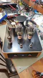

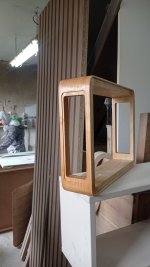
Awesome enclosure. Was that make or buy?My amplifier during the final tests:
And ready for listening:
Where'd you get the meters? I'm having trouble finding ones that small.
I think I am going to attempt using a WS1 with built-in SL15 60002 thermistor.
Either that or adding a CL-90 on the live wire before the transformer primary.
5AR4s are now quite pricey and I can’t keep replacing them.
Either that or adding a CL-90 on the live wire before the transformer primary.
5AR4s are now quite pricey and I can’t keep replacing them.
I noticed you previously mentioned a thermal shutdown on a 5V supply. And now arcing rectifiers. Sounds like something is not quite right somewhere.Another 5AR4 arc’ed tonight. 😞 My supply of those is running low.
How many 5AR4s have arced? What brand(s) 5AR4’s have you lost? JJ’s 5AR4s have been accused of fragility, but many cases of arcing JJ 5AR4s were caused by insufficient resistance in the secondary winding of modern power transformers. (Check a detailed data sheet for the specs on the resistance 5AR4 requires between the anodes.)
More information about your amp would be helpful to identify potential problem areas. Specifically, are you using a choke in place of R4?
3 rectifiers have arc’ed. 1 very early on, 1 after a few weeks and 1 after a few months. Sovtek, Psvane.
I think you are right about “insufficient resistance in the secondary winding of modern power transformers”.
And yes, I use a choke in place of R4.
I remember reading “Remove R4 and connect the choke wires in its place.”
But I also realized:
https://edcorusa.com/products/cxc125-10h-200ma-10h-200ma-choke
Dang the DCR of that choke is only 75R.
So, I am probably doing this to myself.
What’s the best way to fix it. Short of adding a resistor in series with the choke?
I have been waffling badly between putting a WS1T in there
https://www.tedweber.com/ws1/
The WS1T version is diodes + a thermistor
https://www.mouser.com/ProductDetail/Ametherm/SL15-60002?qs=PVyXUKBeRH1eSjGW4kwqbA==
The only reason I stuck with the 5AR4 is the slow start benefit. Although I am not sure I believe in cathode stripping.
Adding a 80R resistor in series with the choke will certainly fix the problem, with thermistors for extra safety, but it’ll drop some B+.
Hence the waffling…
@Francois G @Tubelab_com
I put the amp back on the bench and I’ll keep it there until I am confident everything is “better”. I love this amp and I want it to keep working reliably.
In addition to the data in my previous 2 posts, I just measured the DCR between each end and CT of the HV 330-0-330 secondary winding.
On one side, I get 35.3R and on the other side I get 36.8R.
The 5AR4 data sheet says that a ~90R limiting resistor is recommended per plate.
So, I guess that could be another reason why I have had 5AR4s arcing on power up or shortly thereafter.
So, I think I have all the data I need now, but I am still uncertain about the best remedial strategy.
Resistances needs to be added and/or thermistors, but what’s the best fix?
I put the amp back on the bench and I’ll keep it there until I am confident everything is “better”. I love this amp and I want it to keep working reliably.
In addition to the data in my previous 2 posts, I just measured the DCR between each end and CT of the HV 330-0-330 secondary winding.
On one side, I get 35.3R and on the other side I get 36.8R.
The 5AR4 data sheet says that a ~90R limiting resistor is recommended per plate.
So, I guess that could be another reason why I have had 5AR4s arcing on power up or shortly thereafter.
So, I think I have all the data I need now, but I am still uncertain about the best remedial strategy.
- The choke stands at 75R, which is half the DCR the BOM calls for.
- The HV secondary winding also has much less DCR than the 5AR4 likes to see.
Resistances needs to be added and/or thermistors, but what’s the best fix?
I have been waffling badly between putting a WS1T in there
https://www.tedweber.com/ws1/
The WS1T version is diodes + a thermistor
https://www.mouser.com/ProductDetail/Ametherm/SL15-60002?qs=PVyXUKBeRH1eSjGW4kwqbA==
The only reason I stuck with the 5AR4 is the slow start benefit. Although I am not sure I believe in cathode stripping.
Adding a 80R resistor in series with the choke will certainly fix the problem, with thermistors for extra safety, but it’ll drop some B+.
Hence the waffling…
The 5AR4 is more important for the startup sequence than “preventing cathode stripping”. The 300b bias has to be up and stable by the time B+ rises to the max value.
I don’t know what operating conditions you are aiming for for the 300b outputs. If you could stand to loose a few volts my preference would be to keep the 5AR4 but use inrush current limiters and/or resistors in the PT secondary (or center tap), not adding resistance to the choke (to keep the B+supply as low impedance as possible). I expect if you have sufficient resistance (according to the data sheet) in the 5AR4 anode circuit you will not experience further arcing.
Let us know how this works out. Good luck!
I installed the resistors before the plates of a brand new 5AR4. Checkout didn’t go far though, as B- stays close to zero.
Sometimes you just can’t win.
Sometimes you just can’t win.
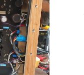
Fixed it. It was special #2, R5 failed open during the previous arcing episode.
I’ll post a picture, it’s remarkable. That resistor looks mint, but is clearly open.
I think the mystery is solved, it must also be a side effect of the same conditions that make rectifiers arc. (not enough limiting resistance before the plates)
I’ll post a picture, it’s remarkable. That resistor looks mint, but is clearly open.
I think the mystery is solved, it must also be a side effect of the same conditions that make rectifiers arc. (not enough limiting resistance before the plates)
There have been some issues with R5 going open. It is rare (yours is the third occurrence) but the original part number for R5 has been removed from the BOM. It was originally chosen for it's surge current rating, but some transformer / input capacitor combinations have proven capable of blowing the part. I recommend a 2 watt or larger metal oxide film resistor for this part. If you put the same part in place of the open resistor, I would change it. This is noted in post #1 of this thread at the bottom. Details can be found in post #420. I tested several different parts and could not get any of them to fail even under extreme conditions beyond where anyone would run their amps.Fixed it. It was special #2, R5 failed open during the previous arcing episode.
There have been some issues with R5 going open. It is rare (yours is the third occurrence) but the original part number for R5 has been removed from the BOM. It was originally chosen for it's surge current rating, but some transformer / input capacitor combinations have proven capable of blowing the part. I recommend a 2 watt or larger metal oxide film resistor for this part. If you put the same part in place of the open resistor, I would change it. This is noted in post #1 of this thread at the bottom. Details can be found in post #420. I tested several different parts and could not get any of them to fail even under extreme conditions beyond where anyone would run their amps.
Thank you, I’ll order and make that change.
I missed that footnote in the first post.
Just FYI, the BOM in the first post still lists the 1W part.
Also, the BOM Notes PDF in the first post doesn’t mention R5.
I added 65 ohm 25W resistors before the 5AR4 plates, so I don’t know if this is still likely to happen, though. But truth be told, I don’t want to find out.
I also need to tweak the value of R3 as filament voltage for the 5842s dropped a bit with those new 65 ohm resistors, it seems. Which is a little weird because the resistors are the HV winding and the filaments are all fed from the 6.3V winding.
OCD will probably kill me because it’s summer and line voltage varies between 115V and 120V during the day as air conditioning units bear on the neighborhood supply.
- Home
- More Vendors...
- Tubelab
- After a 14 year run, the TSE must DIE!