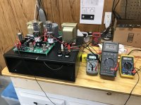
Power transformer questions: I just finished building a TSE and it seems to be working great, in that all my voltages fall in the range they should and the amp sounds good on my small shop speakers. For this build I used a power transformer I had on hand that (per my measurements) could provide appropriate B+ voltage, though I was not sure about its current capabilities. I built the amp using the specified values for all parts except the first cap, which is currently 33uf. I'm using the Edcor 5K OPTs and a nice vintage UTC choke.
After about 1/2 hour burn in time with B+ at 400v and power tube current at about 50ma, I tried cranking the tube current up to 80ma per tube. This caused my B+ to drop to about 368v. While 80ma @368vdc is not a bad operating point, the fact that my B+ dropped so much leads me to believe that my power transformer is a bit undersized in regard to current capacity. I also tried increasing both tube currents up to 90ma (which is probably where I would like to run, though without experimentation I'm not sure yet). This caused B+ to drop to 360vdc. I then reduced the tube currents back to 80ma. After about 1 hour of total run time the PT was quite warm to touch, but not so hot as to be painful to my hand.
Question 1) Is the B+ drop I'm seeing (40vdc between approximately 120ma and 200ma total current draw, which is all 4 tubes with power tubes at 50ma vs 90ma) a big concern, or just typical? And from a sonic perspective, does running the power transformer near or above its current limit cause distortion? This is single ended architecture after all, but I typically over-spec things and try to stay further away from equipment limits.
Question 2) I have the option of upping the first cap to 47uf which will increase my B+ some, but will that help anything? Will that just stress my PT more, but not really address my current limitations? Or does the larger cap actually make the power supply more efficient?
BTW, I'll build a cage to cover the circuit board...
Thanks, G.
Attachments
Another question: I'm using my CD player as the source and using no preamp. I've added volume pots to the amp itself. Does the TSE have any specific requirements re: volume pots? Is the standard audio taper 100K the suggested solution?
Thanks, G.
Thanks, G.
What is your choke resistance? If it is roughly 500 ohms, then the drop makes sense. (40/0.08 = 500)
If the PT is just warm then it doesn't seem like it is being too stressed.
Increasing the first cap can reduce the PSU ripple but the difference is likely not significant.
You can play around with PSUD-II to see what impact it may have.
You can use a 100K audio taper volume pot, but since you're using a CD player, better to use something in the 10K-50K.

Thanks for your thoughts itsikhefez. Can't remember for sure what the resistance of the choke is but I think its closer to 100 ohms than to 500. Testing again last night, the transformer gets rather hot, but not too hot to touch. The job of providing the 6.3vac for all the tube filaments has already been offloaded to a seperate transformer, so the heat is all coming from the B+ and 5v windings.
I would use a 50K or smaller audio taper pot on the TSE and TSE-II amps. I have noticed a measurable high frequency roll off at mid volume settings with a 100K pot due to the miller capacitance of the 5842 tube. Audio taper is designed to make the volume increase as the knob is turned up match the sensitivity curves of an average listener's ears.
Where in the circuit is a Standby switch installed? Is it installed in series with one of the Red HV lines coming off the PT thus disabling the HV to the both rectifiers? Or does it go in series with one of the Yellow 5V lines coming from the PT thus disabling only the V5 rectifier heater?
The original purpose of the standby function was to enable the filaments to be hot so that the B+ could be turned on without waiting for the filaments to heat up, but still have a way to have the amp be "off" as far as amplifying any signal. I think the traditional location was in the ground line for the B+ transformer connection. I've not assessed the TSE circuit to see if that works here.
I am looking at theTSEII schematic. There is really no ground line from the PT. Only the two Red HV wires connected directly to the HV winding in the XFMR. I believe it may be beneficial to implement a standby function to avoid the possibility of cathode stripping by appling HV before the filiments are warmed up?
There is no easy way to implement a standby switch on the TSE or TSE-II. The HV winding makes both positive and negative voltages. The CT (red-yel) wire on the HV is grounded. Do NOT put a switch in this wire as bad things will happen.
The negative supply provides the bias voltages for the output tubes and feeds the source resistor on the mosfet followers. The solid state diodes assure that this negative voltage is present, and sufficient to cut the output tubes off a few milliseconds after switch on. The B+, the positive supply for the mosfet and the positive end of the bias voltage divider is rectified with a 5AR4 tube which warms up quite a bit slower than the typical DHT. This allows the DHT's filament to be sufficiently hot for conduction as the B+ comes up and the bias is pulled up from cutoff.
If you switch, or otherwise disconnect the ground from the CT on the HV winding You will have a large voltage between the B+ and the negative supply with no ground reference. Since the B+ load would attempt to draw more current then the negative supply the negative supply voltage could reach -500 volts or higher blowing the caps or worse.
Attempting to switch the heater of the rectifier is not a good idea either since the 5 volt winding is elevated to the full B+ voltage before the choke. The switch may not be able to handle this voltage and a short here could fry the power transformer or become a serious shock hazard.
Switching one red wire will not shut down the amp. It will only turn the full wave rectifiers into half wave rectifiers increasing hum and possibly overloading one plate in the rectifier tube. Attempting to switch both red wires puts the full HV secondary voltage (550 volts or more) across your switch, again increasing the odds of blown parts or worse.
If you do not understand my explanations it would be wise not to mess with a circuit that is well designed and has worked well for over 15 years. The output tubes remain in cutoff until they are ready if a 5AR4 is used. Some builders use other rectifiers which are usually slower than a DHT but may not be the best choice for a 2A3 since their 2.5 amp filaments are a bit slow to heat.
Copy that! Thank you for the excellent explanation. I do follow your explanation.
Another question. What is the desired plate voltage adjustment on the 5842's?
Also what is the desired plate current for the 5842's. Is there an easy way to verify the plate current in the 5842's since there is the CCS circuit on the plate and the parallel cathode resistance which will be changing as R9, R20 is adjusted. I believe I had read that the CCS is set to 12mA via the 330R R27?
I have a couple of simplistic questions and I apologize for my ignorance as I am a late comer to tubes. I don't seem to understand the schematic, specifically how the 300b heaters are from a single instead of the normally two isolated filament supplies.
I have been reading the power driver and other articles on tubelab, I guess the grounded grid on the output tube allows that? From what I understand it seems like a very clever and unusual design! I am considering using this board.
I have been looking (admittedly not very hard) for info on the proper power transformer(s) requirements. I will use 300B and since the voltage is lower than usual, I am hoping that someone that built this can suggest some power tr alternatives or links with info.
Thanks!
Hi all, I've had my tse2 pcb for what feels a few years now but I'm only now in a position to start a build.
Can I ask, has thee been component supply issues I need to look out for or any developments since release that I'd need to account for with a new build?
Can I ask, has thee been component supply issues I need to look out for or any developments since release that I'd need to account for with a new build?
Hi all, I've had my tse2 pcb for what feels a few years now but I'm only now in a position to start a build.
Can I ask, has thee been component supply issues I need to look out for or any developments since release that I'd need to account for with a new build?
Basically, all the silicon parts vary in availability depending on logistics of the moment or obsolescence strategies by manufacturers.
If you search for posts by me in this thread, you should find substitutions I successfully made this year.
I just ordered the BoM this week. I was able to source everything between mouser and digikey (aside from tubes, sockets, and transformers) except one of the regulators, which I found a sub for in a post on this thread (don't remember specifics). Also the carbon comp resistor. Bought a pack of 100 for a few bucks on eBay.Hi all, I've had my tse2 pcb for what feels a few years now but I'm only now in a position to start a build.
Can I ask, has thee been component supply issues I need to look out for or any developments since release that I'd need to account for with a new build?
I've had a chance to check my orders.
I had to go to ebay for the carbon comp resistor, and the MIC29502WT.
If you are building the 300B version, the 1N5388BRLG diode is on backorder.
STF3LN80K5 is not available, but STF3N80K5 is a likely substitute.
Everything else was on-hand at either mouser or digikey.
I had to go to ebay for the carbon comp resistor, and the MIC29502WT.
If you are building the 300B version, the 1N5388BRLG diode is on backorder.
STF3LN80K5 is not available, but STF3N80K5 is a likely substitute.
Everything else was on-hand at either mouser or digikey.
Ouch, after many weeks of bliss, it seems my 300Bs lost filament supply...to be investigated...
- Home
- More Vendors...
- Tubelab
- After a 14 year run, the TSE must DIE!