George,
I installed D3 and D4 and TR1. The cathodes of D1,2 are absolutely to ground.
I still have (-) 700vDC at the power tube plates.
With tubes removed
there is 410vAC at both secondary taps to ground
The Center Tap is grounded, (0) ohms to ground
The recitifier is a known good tube.
I've gone even blinder verifying orientation of all parts, connections and tube sockets.
It has to be something stupid...it always is. There's no way (I do not have D1 and D2 installed) the SW1's should be jumpered?
Or for that matter the D1, D2 eyelets?
BillEpstein,
In the transformer section of the SSE notes George wrote: “The high voltage secondary should be 700 to 750 VCT (350-0-350) to (375-0-375) it should be rated for at least 175 mA DC output. An 800 VCT (400-0-400) transformer will result in too much B+ voltage and should NOT be used. This winding MUST have a center tap.” You mentioned getting 410-0-410 Vac from the power transformer. Sure you want to use it? If so you will have to be careful managing the B+, based on your power tubes, transformers etc.
I think you bought a brand new PCB, with TR-1, D3 and D4. Where is the schematic? Tubelab.com schematic (that I could find) does not show these components. But I know how the “yellow sheet mod“ places the two SS diodes in series with the vacuum diodes. In looking at you photo in post #1311 and the datasheet for it I believe you have installed both the 1655-S4D05120A-ND in reverse.
If this diagnoses is correct, I don’t know how -700 VAC got across the 5AR4 (it was not installed?) or what it did to any electrolytic caps, so proceed accordingly with caution.
Good luck.
@Tubelab_com
As shown in the pictures above I added a brass standoff under one of the “venting pads” designed for R36, which I have off board.
(I can’t use one of the mounting holes in the corner because it’s too close to the 4-pin tube socket, so I need extra support there.)
That pad is connected to the ground plane of the PCB.
As such, the PCB could be grounded via the chassis (which is connected to earth ground). [I measured less than 0.1 ohm between the ground plane of the board and the IEC inlet earth tab when using the chassis as a ground “wire”.]
But for extra safety, I will also run a wire from the T1-RED_YEL pads to the chassis ground lug.
Hi Francois, I was thinking this must be the unloaded voltage, so allowing for 10% reduction when loaded then it is 369-0-369, which should be in the ball park?You mentioned getting 410-0-410 Vac from the power transformer. Sure you want to use it?
@BillEpstein It is a pity that you fitted those schottky diodes and not the UF4007 that were recommended. For one thing you have the plane surface of the diode next to the plane surface of the ICL, which is a heat sink next to a heat source. The proper diodes on the board would be away from the radiated heat of the CL-140.
Have we seen the way the power transformer is hooked up to the board? I will check back, but mixing up the connections could be an issue, especially if it is designed for 240 and 120 VAC operation.
Cheers, Richard
Hi Guys,
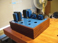
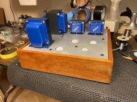
First Pic is my build way back in 2004 or 5 with the same Allied (Hammond) 6K7VG as now. IIRCC the B+ was around 330V with a 5AR4 as now.

That was before the diodes and ICL were added to the current board. All the hookups are exactly the same as before.

Pic #2 is before adding the Diodes, the only voltage spec'd I had on hand and the ICL.
First Pic is my build way back in 2004 or 5 with the same Allied (Hammond) 6K7VG as now. IIRCC the B+ was around 330V with a 5AR4 as now.
That was before the diodes and ICL were added to the current board. All the hookups are exactly the same as before.
Pic #2 is before adding the Diodes, the only voltage spec'd I had on hand and the ICL.
I've built far more complex circuits from schematics including my push pull monoblocks. I wasn't going to let this simple PCB based amp that I've successfully built in the past stop me.
When the going get's rough, the tough go shopping!
Having another fresh PCB due to an USPS screwup I ordered the parts I couldn't salvage from this accursed one and found Hawk Electronics that discounted Hammond 10% to replace the 20 year old 374BX and 193H from my original build .
Do Over!
When the going get's rough, the tough go shopping!
Having another fresh PCB due to an USPS screwup I ordered the parts I couldn't salvage from this accursed one and found Hawk Electronics that discounted Hammond 10% to replace the 20 year old 374BX and 193H from my original build .
Do Over!

There does not look to be so much solder on some of those pads. Maybe reworking the existing board could be worth a try, reflow the joints and add more solder. A joint might have broken at the PCB on a tube base due to swapping tubes.
Can you test your power transformer with no connections, the voltages on the secondaries. If the power transformer is OK, it has to be something to do with the diodes you added or the wiring to the transformer. If the output tubes were not conducting then that would account for a high B+ of around 10%, but it is almost double at 700V, if I understand correctly?
Can you test your power transformer with no connections, the voltages on the secondaries. If the power transformer is OK, it has to be something to do with the diodes you added or the wiring to the transformer. If the output tubes were not conducting then that would account for a high B+ of around 10%, but it is almost double at 700V, if I understand correctly?
I've built far more complex circuits from schematics including my push pull monoblocks. I wasn't going to let this simple PCB based amp that I've successfully built in the past stop me.
When the going get's rough, the tough go shopping!
Having another fresh PCB due to an USPS screwup I ordered the parts I couldn't salvage from this accursed one and found Hawk Electronics that discounted Hammond 10% to replace the 20 year old 374BX and 193H from my original build .
Do Over!
“Do over“ is certainly an option, but I agree vir OldHector. Let’s find the problem first. Then, sure, go ahead and make a shiny new PCB, if that tickles you, and be assured the same mistake doesn’t happen again.
I am curious if you have checked the orientation of the 1655-S4D05120A as shown in #1311? It looks like they are reversed to me.
Question about the photos in #1325 - Did you try to run the new PCB as shown in #1325? I.E., without the new diodes and current limiter?
If not, could you remove those and try. As George pointed out, that part of the new board is the same as before if you used jumpers in place of the diodes and CL-90. Use a known, robust 5AR4, preferably one that worked well in your old PCB, so that arcing of the new generation of 5AR4 is not an issue.
Last edited:
OK, I think I will settle on this bias point with those 3.75K OPTs.
The build is complete, but I failed to completely quiet the Edcor power transformer, so I’ll have to abandon my idea of using this amp with headphones.
Maybe I could try putting an additional bell on it, but heat dissipation could be a problem then.
I also had a new issue Sovtek 5AR4 fail on first power up in the chassis. I replaced it with a Linlai 5U4G. It’s not a soft start anymore, but that will have to do for now.
20 years ago, when the Hammond 200 Series in the Hagerman Coronet was shown to be a vibrating problem, I began to put E.A.R. SD-40 under all my iron.
It cured the 200s and I continue to use it this way no matter the transformer, including Edcor. Michael Percy http://www.percyaudio.com/Catalog.pdf sells it.
It cured the 200s and I continue to use it this way no matter the transformer, including Edcor. Michael Percy http://www.percyaudio.com/Catalog.pdf sells it.
@BillEpstein Thanks, Bill. I did put some butyl based deadening pads in the end bells, but that didn’t help much.
It’s like the bobbin is vibrating.
It’s like the bobbin is vibrating.
I sent an email to Edcor about that buzzing PT.
Very tempted to switch to Hammond, but then I would have a black chunk in the middle of the blue herd.
Very tempted to switch to Hammond, but then I would have a black chunk in the middle of the blue herd.
With the Transcendars no more I was stuck with new Edcor GXSE's and 20 year old Hammond PT and Choke in black. I no longer had an "in" with a local metal finisher so gave in to the blue all around finding that Krylon True Blue from Lowe's is close enough to the Edcor as makes no difference. I just scuff sanded the Hammonds and sprayed.
E.A.R., BTW, is an industry leader in aerospace and marine vibration suppression with DoD contracts. The SD-40 is not some audiophile nonsense and should go between your iron and top plate.

E.A.R., BTW, is an industry leader in aerospace and marine vibration suppression with DoD contracts. The SD-40 is not some audiophile nonsense and should go between your iron and top plate.
Attachments
@BillEpstein I ordered sorbothane washers.
The SD-40 might come next, or a Hammond transformer with your paint advice.
Depending on what Edcor replies.
The irony is that PTs I got from China did not buzz.
The SD-40 might come next, or a Hammond transformer with your paint advice.
Depending on what Edcor replies.
The irony is that PTs I got from China did not buzz.
@Tubelab_com As I am about to wrap up this project, I figured I would add the motor run capacitor and I did. On first power up, after that, I got a spark in the C5 / R30 area, so I immediately cut power.
After inspection, I saw no damage components. I removed the motor run capacitor and powered things again.
No spark this time, and all voltages are as perfect as ever.
Based on your experience, what happened?
After inspection, I saw no damage components. I removed the motor run capacitor and powered things again.
No spark this time, and all voltages are as perfect as ever.
Based on your experience, what happened?
Based on your experience, what happened?
@Tubelab_com Based on the location of the spark, thinking it might have been the diode that piggybacks R30.
It doesn’t appear to be busted, though.
Are you sure that the motor run cap that you tried is a motor RUN cap and not a motor start cap? A start cap is usually an electrolytic and often comes in a plastic can. They are not meant for continuous use. They will often short out, vent or burst if used in a tube amp. A run cap is usually polypropylene and rated for continuous use. They are usually in an aluminum can. The cap should be about 100 uF or less and should be connected from the yellow wire on your choke to ground (in parallel with C5).
The spark you saw likely happened inside the rectifier tube. That's about the only place it could happen without causing some visible damage. When a diode dies, they nearly always short, which should blow the mains fuse. The diode across R30 is not needed on a TSE-II board. It was added to original TSE boards, but it became D7 on the TSE-II, you can remove the diode on R30, though there's no harm in leaving it there. Another possibility is that R30 itself was touching the PC board ground which would require some damage in the coating of the resistor or the board itself. The resistor should be spaced a few mm above the board to prevent this.
The spark you saw likely happened inside the rectifier tube. That's about the only place it could happen without causing some visible damage. When a diode dies, they nearly always short, which should blow the mains fuse. The diode across R30 is not needed on a TSE-II board. It was added to original TSE boards, but it became D7 on the TSE-II, you can remove the diode on R30, though there's no harm in leaving it there. Another possibility is that R30 itself was touching the PC board ground which would require some damage in the coating of the resistor or the board itself. The resistor should be spaced a few mm above the board to prevent this.
Are you sure that the motor run cap that you tried is a motor RUN cap and not a motor start cap? A start cap is usually an electrolytic and often comes in a plastic can. They are not meant for continuous use. They will often short out, vent or burst if used in a tube amp. A run cap is usually polypropylene and rated for continuous use. They are usually in an aluminum can. The cap should be about 100 uF or less and should be connected from the yellow wire on your choke to ground (in parallel with C5).
The spark you saw likely happened inside the rectifier tube. That's about the only place it could happen without causing some visible damage. When a diode dies, they nearly always short, which should blow the mains fuse. The diode across R30 is not needed on a TSE-II board. It was added to original TSE boards, but it became D7 on the TSE-II, you can remove the diode on R30, though there's no harm in leaving it there. Another possibility is that R30 itself was touching the PC board ground which would require some damage in the coating of the resistor or the board itself. The resistor should be spaced a few mm above the board to prevent this.
Thank you, George. Pretty sure it’s a motor run cap, unless Digi-Key lies:
https://www.digikey.com/en/products...N8dlZgyaaBMAT9h22xNFDE56KtZn0Vg_-SmlRQIqQqnWw
I also have a 10A fuse inside the chassis and it didn’t blow, so the diode certainly didn’t short. If it failed, it must have failed open. But since it’s not needed, I’m not going to worry about it anymore.
Is it possible that adding that 100 uF motor run cap in parallel with C5 caused enough inrush current to make the rectifier arc?
It’s remarkable the rectifier survived and still works fine without the motor run cap.
- Home
- More Vendors...
- Tubelab
- After a 14 year run, the TSE must DIE!