I am confident that your build will be fine if you follow the supplied BOM and directions. As you mentioned many had been built successfully. But, like you I enjoy knowing the performance characteristics and effects of the parts, hence the interest in PSUD2 simulation.
The PS equivalent load resistor will depend on operating conditions, including B+ and tubes in use and their bias. What output tubes are you planning to use? (I guess 300b). That will primarily determine what your load current is, since the 5842 tube and Q1,2 will be a lot less. George says (in the “Applications” section the 300 B tubes should be biased for 60-75 ma per tube, so let’s say you bias it at 60 ma each. That means your guess of 150 ma total is close to correct for the whole amp, perhaps a little low, but let’s use it for now. I guess you are targeting a B+ of say 360 Vdc. So, your “load resistor” has to drop 360 volts at 150 ma, which represents a resistance of 2400 ohms. Try adding a 2400 ohm load resistor to your PSUD2 circuit and see what PSUD2 results you get. Good luck.
The PS equivalent load resistor will depend on operating conditions, including B+ and tubes in use and their bias. What output tubes are you planning to use? (I guess 300b). That will primarily determine what your load current is, since the 5842 tube and Q1,2 will be a lot less. George says (in the “Applications” section the 300 B tubes should be biased for 60-75 ma per tube, so let’s say you bias it at 60 ma each. That means your guess of 150 ma total is close to correct for the whole amp, perhaps a little low, but let’s use it for now. I guess you are targeting a B+ of say 360 Vdc. So, your “load resistor” has to drop 360 volts at 150 ma, which represents a resistance of 2400 ohms. Try adding a 2400 ohm load resistor to your PSUD2 circuit and see what PSUD2 results you get. Good luck.
Last edited:

You can add a current load in PSU2 to represent the current draw of the amp.
Apply a delay time to the current load and you can visualise the effect of loading the power supply.
Thank you. I changed the load resistor to a 150 mA current sink and everything looks fine. With B+ settling at ~400V, after a 440V peak.
I am confident that your build will be fine if you follow the supplied BOM and directions. As you mentioned many had been built successfully. But, like you I enjoy knowing the performance characteristics and effects of the parts, hence the interest in PSUD2 simulation.
The PS equivalent load resistor will depend on operating conditions, including B+ and tubes in use and their bias. What output tubes are you planning to use? (I guess 300b). That will primarily determine what your load current is, since the 5842 tube and Q1,2 will be a lot less. George says (in the “Applications” section the 300 B tubes should be biased for 60-75 ma per tube, so let’s say you bias it at 60 ma each. That means your guess of 150 ma total is close to correct for the whole amp, perhaps a little low, but let’s use it for now. I guess you are targeting a B+ of say 360 Vdc. So, your “load resistor” has to drop 360 volts at 150 ma, which represents a resistance of 2400 ohms. Try adding a 2400 ohm load resistor to your PSUD2 circuit and see what PSUD2 results you get. Good luck.
A resistive load of 2.4K yields the same predictions as a 150 mA current sink. So, I think we are on the right track.
Looking forward to seeing how reality matches these predictions.
For C9 and C11, the coupling capacitors, the BOM says 0.1uF at 450V or better, but lots of people seem to install 0.47uF, 0.68uF or even 1uF caps...
Does it make a difference as long as they are good quality?
Does it make a difference as long as they are good quality?
The BOM I looked at on Tubelabs website says 0.22 uF @ 400 V min. (http://tubelab.com/designs/tubelab-se/parts-list/) Is there a more recent BOM?
I would not go higher than 0.22 uF that George specified. Larger capacitors will allow lower signals to pass, than George’s design intended and I see no benefit in trying to drive subsonic signals to your speakers. Bass is not why you want a SET in the first place.
My experience had been that the smallest capacitor that will pass the lowest frequency I need to pass is the best sounding one.
@Francois G Yes, the most recent BOM is attached to the first post of this thread. I attached it here too.
I’ll go with the recommended 0.1uF for now.
I’ll go with the recommended 0.1uF for now.
Attachments
Also, for those who come after me, tubelab.com refers to the TSE, not necessarily the TSE-II. It's largely the same thing except some of the photos show a different board layout.
And, when it comes to jumpers, only PAD1, PAD3 and PAD4 remain.
For 300B and 5V filaments, you install a jumper between PAD3 and PAD4.
And, when it comes to jumpers, only PAD1, PAD3 and PAD4 remain.
For 300B and 5V filaments, you install a jumper between PAD3 and PAD4.
Checkout in progress...
Everything was according to plan until I arrived at checking the plate voltage of the 5842s. I basically have very little voltage between plate and ground. (~1 to 2V) And the trimmers are powerless to change this.
I'm wondering if these 10M45S parts I got from China are fake.
It would be annoying, as I soldering those heatsinks pretty tight.
Well, I went ahead and removed those parts from the board.
IC1/2 are really the only thing between B+ and the plates of the 5842s, so I concluded it had to be the culprit.
It didn't go too bad. 1 trace lost a bit of varnish and the copper is exposed a bit, but continuity still exists where it should.
Now I’ll wait for DK to deliver real parts. Apparently they got it back in limited quantities.
Yeah, the timing was good I guess or terrible, as I would never have ordered them from China if they had been available from Mouser or DK in the first place.
My rework game is very weak, so I always dread those situations. Hopefully, it gets back on track, or I’ll repurpose those transformers and other parts for something else.
My rework game is very weak, so I always dread those situations. Hopefully, it gets back on track, or I’ll repurpose those transformers and other parts for something else.
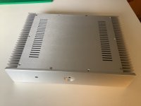
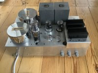
I finally got my new chassis and I’m ready to build my new Tse! The old one died a few years ago after extensive modding (second picture). I‘m not going to mod anymore (George : I promise!). I am hoping to take advantage of those amazing heatsinks on the new chassis by moving hot components off the board. Which should I move? IC1/2 R36 Q1/2? IC3 and D1? Thanks! Henry
Attachments
New 10M45S parts came from DK today and were promptly installed.
Now I got numbers to share…
5AR4 heater voltage = ~5.2V
Raytheon 5842 heater voltage = ~5.42V and ~5.44V
300B heater voltage = ~4.93V and ~4.93V
B- = ~-186.6V
B+ = ~368.5V when ~65 mA go through R18 and R29.
So, this first checkout is pretty good, but I am a little concerned about the filament voltage of the 5842s. It’s low, isn’t it? Typical would be 6.3V, right?
I didn’t connect the CT of the 6.3V secondary winding, could that be the reason?
Or maybe the Raytheon specs are a little different.
I have Amperex to try in their place, which I didn’t want to plug in during the initial checkout. I’ll try with those tomorrow.
If @Tubelab_com George or anyone else could comment in the numbers above I would greatly appreciate it! Thanks!
The heater voltage on your 5842 should somewhere between 5.7 and 6.9 volts. The CT of the 6.3V secondary is not needed for a 5 volt tube like the 300B. You may need to reduce the value of R3 slightly to get the voltage in that range. The resistor value is quite dependent on the power transformer and line voltage. I tend to use Hammond power transformers which are a bit generous in voltage so the value in the BOM may be too big for a different transformer.
@Tubelab_com Thanks! I should probably have gone with Hammond. That Edcor PT has a buzz to it too, which is annoying.
The heater voltage on your 5842 should somewhere between 5.7 and 6.9 volts. The CT of the 6.3V secondary is not needed for a 5 volt tube like the 300B. You may need to reduce the value of R3 slightly to get the voltage in that range. The resistor value is quite dependent on the power transformer and line voltage. I tend to use Hammond power transformers which are a bit generous in voltage so the value in the BOM may be too big for a different transformer.
Adding temporary resistors in parallel with R3 tells me I need to replace R3 with a 0.75R resistor to get ~6.2V at the filament of those 5842s.
I didn't expect to have to drop it that low.
- Home
- More Vendors...
- Tubelab
- After a 14 year run, the TSE must DIE!