So, Newark emailed and STF3LN80K5 is unobtainium for now.
Would STF3N80K5 be a suitable replacement?
Would STF3N80K5 be a suitable replacement?
They should work, but I don't have any and have never tried them.So, Newark emailed and STF3LN80K5 is unobtainium for now.
Would STF3N80K5 be a suitable replacement?
They should work, but I don't have any and have never tried them.
Is there a way to find out without blowing something up?
I ordered a few pieces.
Hi csample. George's idea sounds like a good plan if you still want to go that route.
I used to embrace symmetrical layouts when I began building DIY electronics (amateur radio and audio) in earnest some 20+ years ago. As I've acquired more experience, the technical and aesthetic merits of asymmetrical layouts have become more and more apparent, and I've since become a huge fan of them. Most of this was spurred on by the Tubelab designs and some others, perhaps most notably Poindexter's Musical Machine. All of these have proven that a well-executed asymmetrical amp can be quite elegant.
Regarding heat buildup in the chassis, my experience with the TSE-II has shown that the major culprits are the power transformer (particularly the Hammond 27X-series I'm using), the heatsinked components (filament regulator, CCS chips, driver transistors) and power resistors. Paradoxically, the tubes themselves aeren't really a big contributor. Use mongo heatsinks, provide plenty of convective cooling (i.e. lots of strategically-placed holes), and you'll be fine. I'd even posit that a move away from the Pesante chassis may be a step back in terms of overall conductive dissipation, but I don't know your amp like you do.
I've attached a picture of the 2A3 TSE-II I built last year. The chassis is made of maple and aluminum, and measures 12" x 12" x 4". Despite its small size, radiant and conductive heat from the tubes is a non-issue.
Gorgeous build!
@Tubelab_com As I embark on the assembly journey, I realize my boards are v1.3 from 2020, while the BOM in the first post of this very long thread is from 2019. After reading this thread, I concluded this is fine. If I am deluding myself, please reply to this post.
The newer rev in the board number only reflects a change in PC board supplier as the supplier that I had used for 15 years screwed up 4 out of the last 5 orders I placed. The v1.2 and v1.3 boards are identical except for a slight difference in color and weight. The later board are darker and a few grams heavier. All parts are the same.
The newer rev in the board number only reflects a change in PC board supplier as the supplier that I had used for 15 years screwed up 4 out of the last 5 orders I placed. The v1.2 and v1.3 boards are identical except for a slight difference in color and weight. The later board are darker and a few grams heavier. All parts are the same.
Excellent, put on all the resistors this morning, including the piggyback diode on R30, eheh.
Hi @ all,
looking for a little advice:
Am just about finishing a TSE-II and recently read a note of George changing the values of R14 and R25 in dependency of B+ on the old TSE.
Is it still necessaray to do this on the TSE-II or can 20k be used under any condition?
looking for a little advice:
Am just about finishing a TSE-II and recently read a note of George changing the values of R14 and R25 in dependency of B+ on the old TSE.
Is it still necessaray to do this on the TSE-II or can 20k be used under any condition?
Last edited:
Hey George,
I'm down to connecting the inputs and outs and noticed this newer board has 5 eyelets for the inputs, the middle three all to ground. I have a vague memory of connecting the RCA grounds together and running a wire to the star ground on the old board with 4 eyelets. I can use the fifth eyelet to ground and keep the RCA ground tabs separate instead, yes?
All the iron is steel bolted to the conductive top plate so just grounding the IEC to one lug and another wire from the RCA ground to that lug should be all I need? Or should I keep safety ground and board ground separate?
Both boards have 5 eyelets. All are connected together right at the connector with a single trace running to the star ground point. There should be no current flow through this path, just low voltage audio. Any ground current from the IEC connector could inject hum into the signal at this point.
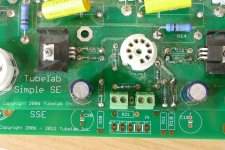
The picture shows the very first SSE board I built with a new version underneath it. The only differences are the name change for legal reasons, and the added diodes and thermistor near the rectifier tube.
If the amp worked good the way it was initially assembled, I would start there and get the new board working. Then make one change at a time and verify it. If you make several changes at once, including the new board, then have a problem it's very hard to determine what caused the problem. I tend to favor running the IEC ground to the T1-red-yel point which has a fat trace to the star ground point which is the negative end of the main filter cap.
Attachments

My memory was a little faulty. I've reached the age where I don't just forget why I walked into a room...I don't recognize it.
My first SSE almost 20 years ago, according to the pic, I ran IEC ground and the grey wire from the PT to the metal chassis (top middle) and that's it.

It was dead quiet and sounded great.
So that's what I've done now except with the wooden chassis the 2 grounds are to a transformer bolt (right side below caps.

Are you suggesting taking the IEC ground to the Red/Yellow wire?
My first SSE almost 20 years ago, according to the pic, I ran IEC ground and the grey wire from the PT to the metal chassis (top middle) and that's it.
It was dead quiet and sounded great.
So that's what I've done now except with the wooden chassis the 2 grounds are to a transformer bolt (right side below caps.
Are you suggesting taking the IEC ground to the Red/Yellow wire?
So, I am taking all the time in the world because I am in not rush at all...
I am using PSUD2 to attempt to simulate the power supply of the 330B TSE-II I am buidling...
The power transformer will be the Edcor XPWR-178...
Edcor doesn't say anything about load regulation, so I used the 330V nominal voltage...
Similarly, ESR of the caps is unspecified, so I put in 0.1 ohm.
I measured DC resistance of the PT primary winding, and DC resistance between the 330V tap and the CT of the secondary.
I also measured the DC resistance of the choke.
PSUD2 shows me this:

If I am to believe this, B+ will be too high and the voltage rating of C4 and C5 (450V) will be too low.
Questions:
I am using PSUD2 to attempt to simulate the power supply of the 330B TSE-II I am buidling...
The power transformer will be the Edcor XPWR-178...
Edcor doesn't say anything about load regulation, so I used the 330V nominal voltage...
Similarly, ESR of the caps is unspecified, so I put in 0.1 ohm.
I measured DC resistance of the PT primary winding, and DC resistance between the 330V tap and the CT of the secondary.
I also measured the DC resistance of the choke.
PSUD2 shows me this:
If I am to believe this, B+ will be too high and the voltage rating of C4 and C5 (450V) will be too low.
Questions:
- Am I using PSUD2 correctly?
- Is B+ going to be too high as PSUD2 implies?
- Should I order new C4 and C5 with a higher voltage rating?
I‘m still a PSUD2 learner but I see only the 150k bleeder resistor and no load. I believe we will like the results better if the equivalent load resistance is added (i.e. how much you estimate your amplifier will draw under steady state.) That should lower your PS voltage. I believe PSUD2 takes in account the slow startup of the 5AR4, but not the variation in load as the power tubes warm and begin to conduct. Whether your caps will be OK depends on what caps you bought. Most caps specify some allowable overvoltage for startup purposes - 10% or so.
I’m not sure how to interpret I (C1). I assume one has to ascertain that C1 can handle the ripple current (IC1?) PSUD2 predicts. Is your simulation showing a max for I(C1) of 35.7 amps, and ID1 824 something? Can’t be. I hope someone more knowledgeable could clarify for us.
I’m not sure how to interpret I (C1). I assume one has to ascertain that C1 can handle the ripple current (IC1?) PSUD2 predicts. Is your simulation showing a max for I(C1) of 35.7 amps, and ID1 824 something? Can’t be. I hope someone more knowledgeable could clarify for us.
Last edited:
@Francois G Merci !
I am new to PSUD2 as well.
To be honest, I don’t quite know how to quantify the overall load of the circuit.
I am new to PSUD2 as well.
To be honest, I don’t quite know how to quantify the overall load of the circuit.
What I had done regarding the load resistor estimate (for a different amp that I simulated) is to add up the estimated currents flowing through all the driver and power tubes under no load and then added (arbitrarily) 20% for music peaks.
After looking at the schematic it seems that there are 3 things in paralel to consider in the load calculation in each amp. The CCS currents (V1&2), the current through Q1&2 and the power tube currents (V3&4). The Vs you should be able to get, but I dont know the Q currents.
Anyone with information on these currents?
Anyone with information on these currents?
@Francois G I really appreciate your help with this, but these certainly depend on various operating conditions. (obviously, I know)
The documentation states that the HV winding of the power transformer should be able to deliver at least 150 mA, so maybe we can use that as a coarse measure of the overall load of the circuit?
How would one represent that in PSUD2?
I think I might just build with the supplied BOM and carefully measure everything under variac and in stages.
Many have built this amp, so maybe I worry about nothing.
It would still be nice to know if such things can be estimated ahead of time without live experiments, but maybe that’s not possible.
You can add a current load in PSU2 to represent the current draw of the amp.
Apply a delay time to the current load and you can visualise the effect of loading the power supply.
Apply a delay time to the current load and you can visualise the effect of loading the power supply.
- Home
- More Vendors...
- Tubelab
- After a 14 year run, the TSE must DIE!