The factory symbol resembles an asterisk, which looks to be the code for the Amperex tube factory in New York, so that settles that.
But according to the document I downloaded, VK is 5842 417A, so still unclear about which type it might be ...
Win W5JAG
But according to the document I downloaded, VK is 5842 417A, so still unclear about which type it might be ...
Win W5JAG
There are several Philips code lists online.
The one that is an actual scan of an old document only says 5842.
The ones that are actually readable look like somebody took the time to type it all in a spreadsheet.
My vote is for the 1960s papyrus scroll 😉
The one that is an actual scan of an old document only says 5842.
The ones that are actually readable look like somebody took the time to type it all in a spreadsheet.
My vote is for the 1960s papyrus scroll 😉
I have several pentode driving pentode amps in the works. Two are working prototypes now. The unique thing is the triode curves I'm tricking those pentodes into giving me. The curves ARE evenly spaced.
Way cool!
Tom
A nice set of curves indeed.
And 50-80W from small sweeps is impressive (again).
Not being familiar with US sweep types, are these comparable in size to the European EL36?
I get 50W from those, but that's in pentode mode.
(sorry for getting of topic)
And 50-80W from small sweeps is impressive (again).
Not being familiar with US sweep types, are these comparable in size to the European EL36?
I get 50W from those, but that's in pentode mode.
(sorry for getting of topic)
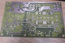
For folks who want to mount MOSFETs on the underside of the TSE PCB
George,
Some folks have mounted the MOSFETs on the underside of the PCB vs the top. Others want to do that so the input tubes are more visible. Understand that some of the heat gets trapped underneath the PCB if the MOSFETs are mounted on the underside.
Would having a few holes near the MOSFET area (now bigger in the new proto design) help the heat escape through the top? Some PCBs have small vias - in this case, probably slightly bigger holes would help. In turn the builder would have to make slits/holes on his top plate corresponding to the MOSFET area of the PCB to allow the heat to escape through the top of the chassis.
https://www.diyaudio.com/forums/tubelab/157491-pictures-tubelab-amp-46.html#post5708968
Not being familiar with US sweep types, are these comparable in size to the European EL36?
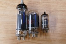
I don't know the EL36, so here is a picture of the tube, a 6GF5 in between a 13GB5 / XL500 and a 6DJ8 / ECC88. Don't let its 9 watt plate rating fool you. It's a 6DQ6 stuffed in a tiny bottle. It's plate fins are gone, so you cant squeeze 100 watts from a pair like the 6DQ6.
Some PCBs have small vias - in this case, probably slightly bigger holes would help.
I'm trying to fit some in now for the next test board. This one will be built with the parts on the bottom to verify fitment. Then I will stick it in a tiny box and cook it to see how hot it gets. Right now the resistor that drops voltage for the mosfets gets hotter than the mosfets themselves, so I'll need to tinker with the zener voltage to balance it all out.
Attachments
They're ALL GONE!
I will mail out the last TSE board tomorrow morning....except for the one I will build. I built the very first TSE, and I will build the very last TSE......
I already have the very first TSE-II and number two isn't far away.
I will mail out the last TSE board tomorrow morning....except for the one I will build. I built the very first TSE, and I will build the very last TSE......
I already have the very first TSE-II and number two isn't far away.
Thanks, George! I'll be one of the first in line when they're ready.
Around Christmas of last year (2018), I was within an ace of ordering a TSE board until I noticed the Sharp voltage regulator was obsolete and out of stock. Finding a replacement MOSFET driver wasn't a big deal, but in my mind the need to kludge a different regulator rather defeated the purpose of building on a PC board to begin with. I've always admired the circuit and thought it deserved better. And it just didn't seem right to build one point-to-point without at least ordering a board - but I have enough unused "stuff" around the house already.
So thanks again for all your hard work on the new board. I can't wait to get started... 🙂
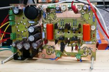
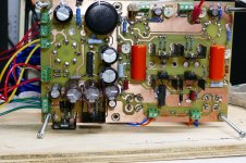
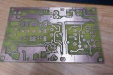
Wednesday was an uncharacteristic warmish (50F) sunny day, so I spent much of it outside with a piece of copper clad, some ferric chloride, and a drill press. At the end of the day I had a bare prototype board that incorporated several more changes, and had more holes than a block of Swiss cheese. (first two pics).
Yesterday was the second of two nice days, with the threat of snow last night but I resisted the temptation to play outside, and spent it in the basement with a soldering iron. Sometime around 6PM the board was populated. I wired up the 6.3 volt leads from the power transformer, and plugged it in. I had 2.48 volts at the 2A3 sockets.....good.
I added the HV wires from the power transformer, plugged it in and poof there was some smoke and two halves of the R5 resistor remained where a whole one had been. It didn't take me long to realize that both C6 and C7 were in BACKWARDS, and I had only ordered two pair.....not so good.
After stuffing my face with leftovers, I turned the backward caps around, replaced R6, and tried again. No smoke, plenty of negative voltage......good.
I wired up the 5 volt winding from the power transformer, and the choke, plugged in a 5AR4, and fired it up again. No B+. When you make your own PC boards, it's nearly impossible to do plated through holes, so you must solder the components on both sides ov the board to make the through connection is it is needed. I had missed a solder connection on the 5AR4 socket. After fixing that, I had B+, and the grid voltage at the output tube sockets would adjust from -25 volts to -90 volts........also good.
I installed the 5842's and set their plate voltage to 175 volts without issue. I popped in some 2A3's and set their bias to 70 mA each.....good. I hooked up some speakers, and touched the inputs....no buzz......not so good. It was late, I killed power to the bench and walked away. During the 3 evening hours my front yard had gone from green, to white......not so good, I fetched the snow shovels, a broom, and the gas can for the snow blower from the shed and went to bed wondering what could be wrong.....
This morning I cleared the driveway, and one of the cars, and set out for the gym. Upon returning I flipped the board over to look at the bottom, to compare it with the good one, and it was obvious. I had not installed any coupling caps. A pair of big fat Orange Drops and I had sound......good sound. I beat on it a bit today and will test it some tomorrow.
Due to some other commitments necessary to pay the bills, this will likely be the version I send out to the board house, unless I find a problem in testing.
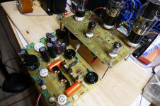
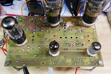
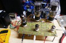
There are now two working proto boards. One was built with parts on the top. The other was build with the tubes on top, but all the other parts on the bottom. There are mounting holes for all partd to be on either side, except for the tube sockets, they MUST be on the top.
Yesterday was the second of two nice days, with the threat of snow last night but I resisted the temptation to play outside, and spent it in the basement with a soldering iron. Sometime around 6PM the board was populated. I wired up the 6.3 volt leads from the power transformer, and plugged it in. I had 2.48 volts at the 2A3 sockets.....good.
I added the HV wires from the power transformer, plugged it in and poof there was some smoke and two halves of the R5 resistor remained where a whole one had been. It didn't take me long to realize that both C6 and C7 were in BACKWARDS, and I had only ordered two pair.....not so good.
After stuffing my face with leftovers, I turned the backward caps around, replaced R6, and tried again. No smoke, plenty of negative voltage......good.
I wired up the 5 volt winding from the power transformer, and the choke, plugged in a 5AR4, and fired it up again. No B+. When you make your own PC boards, it's nearly impossible to do plated through holes, so you must solder the components on both sides ov the board to make the through connection is it is needed. I had missed a solder connection on the 5AR4 socket. After fixing that, I had B+, and the grid voltage at the output tube sockets would adjust from -25 volts to -90 volts........also good.
I installed the 5842's and set their plate voltage to 175 volts without issue. I popped in some 2A3's and set their bias to 70 mA each.....good. I hooked up some speakers, and touched the inputs....no buzz......not so good. It was late, I killed power to the bench and walked away. During the 3 evening hours my front yard had gone from green, to white......not so good, I fetched the snow shovels, a broom, and the gas can for the snow blower from the shed and went to bed wondering what could be wrong.....
This morning I cleared the driveway, and one of the cars, and set out for the gym. Upon returning I flipped the board over to look at the bottom, to compare it with the good one, and it was obvious. I had not installed any coupling caps. A pair of big fat Orange Drops and I had sound......good sound. I beat on it a bit today and will test it some tomorrow.
Due to some other commitments necessary to pay the bills, this will likely be the version I send out to the board house, unless I find a problem in testing.
There are now two working proto boards. One was built with parts on the top. The other was build with the tubes on top, but all the other parts on the bottom. There are mounting holes for all partd to be on either side, except for the tube sockets, they MUST be on the top.
Attachments
-
 P2360480_x.jpg804.6 KB · Views: 444
 -
 P2360477_x.jpg792.1 KB · Views: 455
 -
 P2360476_x.jpg793.3 KB · Views: 387
 -
 P2360475_x.jpg778.7 KB · Views: 424
 -
 P2360473_x.jpg820 KB · Views: 480
 -
 P2360472_x.jpg864.9 KB · Views: 960
 -
 P2360463_x.jpg742.1 KB · Views: 995
 -
 P2360458_x.jpg739.5 KB · Views: 994
 -
 P2360457_x.jpg747.1 KB · Views: 1,057
Any of the parts can be placed on either side of the board except the tube sockets which must be on the top.
It's up to the amp builder whether they want holes in the top plate or a removable top plate to adjust the bias, or to adjust from the bottom. It will work either way.
I plan on close fitting this board to a 1/8 inch thick aluminum plate, so I will adjust from the bottom. This will be a conventional wood base - metal top type of amp.
I haven't yet decided which tubes either amp will get, but I plan to test both boards with the 3 usual choices in the next few days.
The other board with all the parts on the top might go into a rack mount cabinet. If it does it could end up with sweep tubes since they are more suited to horizontal mounting on "L" brackets behind the board. Much of my early sweep tube testing was actually done with a TSE board. They play well together.
The other possibility is a conventional wood base with a clear Lexan top and some "bling" to dress up the guts. I still have such a chassis I made for a TSE and never used, so that choice may be used for the "last TSE."
It's up to the amp builder whether they want holes in the top plate or a removable top plate to adjust the bias, or to adjust from the bottom. It will work either way.
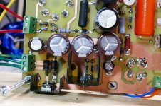
A li'l neat trick I used in my DG300B was to mount the bias adjustment pots on the same side of the board as the tube sockets and drape them with heat shrink tubing. Shrink the tubing and there's enough left to get a screwdriver into the pot. I trimmed this to length, such that it would meet with the top plate of the chassis right where the bias adjustment hole was. It basically makes it such that you can stab a screwdriver in there without fearing that you'll short out any of the connections around the pot.
Just an idea...
Tom
I stole an idea from Tektronix I believe. You drill a hole in the top plate right over the adjustment pot, then pound a short length of hobby shop brass tubing into the hole. You can add a fillet of epoxy under the deck if you want. Then grind the ridges flush on the top side before painting. This way a screwdriver has nowhere to go except to the pot.
Some builders want a no holes look, and some even use a double top approach to cover the mounting screws.
Some builders want a no holes look, and some even use a double top approach to cover the mounting screws.
I just put holes above the pots and use a ceramic screwdriver whose body just fits through the hole so that it can only go straight down. No chance of it touching anything other than the pots.
For a 5842 replacement option in a future amp would a 6em7 be an option? I was reading a review on the Israel Bloom Frankenstein 300b amp, the review was very favorable. I guess it needs it's own transformer tho…
I'm not familiar with that amp, but the 6EM7 is a dual dissimilar triode intended for TV vertical sweep duty. It is about the same size as the 5AR4 rectifier. Neither triode is suitable for driving a 300B alone, so that amp must be a 3 stage design. This would be something totally different than the TSE, and require a whole new design.
I have used the 6EM7 / 6EA7 tubes in the past and found them quite variable. The gain in the first stage (small triode) varies considerably from tube to tube, so some sort of matching is needed.
The 6EM7 is useful when a very large drive signal is needed. I had such a need for a test amp design a while back.
I used it in an amplifier design that I did for a magazine contest over 10 years ago. I needed a lot of drive voltage for a SET amplifier that ran a cathode follower output stage. The cathode follower output stage was chosen for its very high power supply rejection ratio.......the B+ supply can vary or be noisy without affecting the audio output quality. This allows for use of a continuously variable plate supply to improve efficiency. Plate efficiency is the limiting factor in SE amplifiers, so boosting the can make dramatic gains in the power output from a given tube.
The TSE was somewhat ahead of it's time, and was initially rejected and criticized for its CCS load and mosfet driver. It took a while for people to hear them and decide that some properly applied silicon can actually make for a good sounding amp......I'm still not sure if the world is ready for an SE 300B amp with a DSP modulated power supply though even if it did make 25 watts. Thoughts?
In case anyone IS interested the original Circuit Cellar magazine article from 2009 is included. It manage to get 38 watts from a single 6AS7 tube and improve the THD at low power levels in a SE amp. The same amp without supply modulation makes 9 watts. The driver tube in both cases is a 6EM7, the smaller two tubes in the picture.
Attachments
This isn't the review I read...can't seem to find it, but here's another one praising it.Coincident Speaker Technology Frankenstein II Tube Monoblock Amplifier | The Absolute Sound
... I'm still not sure if the world is ready for an SE 300B amp with a DSP modulated power supply though even if it did make 25 watts. Thoughts? ...
I think it's a brilliant idea, and shocking that a decade has passed, but no one has followed up on it.
If a 40 watt 300B can get 25 watts out, what could a KT-150 or KT-120 possibly do? 50 - 60 watts?
If it gets in the product pipeline, will ( would ) it be a separate controller board that can be integrated into existing designs, or is it a hand / glove relationship between the amp and controller, in other words, the two are specifically made for each other?
One drawback that I can see is that for people ( like me ) who have no digital knowledge or experience, it could be a technical support nightmare walking us through problems. High voltage and PIC's on one board look like a big opportunity for things to go poof, fast.
Lastly, make it SMD, no components smaller than 0805, preferably 1206, please ...
Win W5JAG
- Home
- More Vendors...
- Tubelab
- After a 14 year run, the TSE must DIE!