Hi Jeremy, I've had a bit of a play with these two drivers and I can see why they are giving you grief! What I said earlier about just trying to get some good matches to 4th order accoustic isn't as easy as it sounds! (easy enough to get the slope but the phase is quite problematic).
I started to go down the path of 3rd order butterworth slopes with a gap (ie different targets for tweeter and woofer).... That looks like it might be promising. The odd thing is that usually an odd order butterworth has 90 deg phase difference, and revesing phase has not much effect, but this is looking more like it will have good phase matching. Anyway just thought I'd post in case you are banging your head on the wall 😀
Tony.
Had a bit of a break from crossover designing 😛
How does this look:
I started with 3rd order Butterworth slopes and boxsim optimised it to this.
Thanks, Jeremy
How does this look:
An externally hosted image should be here but it was not working when we last tested it.
An externally hosted image should be here but it was not working when we last tested it.
An externally hosted image should be here but it was not working when we last tested it.
I started with 3rd order Butterworth slopes and boxsim optimised it to this.
Thanks, Jeremy
Like it was designed by a simplistic optimiser? 😀How does this look
I though, that's precise phase matching on axis, but at 4k this crossover seems to be letting a slight phase difference occur that is reducing the summing around that woofer peak.
Not only is this peak a little close to the primary level, for my liking but running it out of phase at all wouldn''t be the right way to handle it.
The impedance peak is a little off in frequency, might be a concern.
The thing with these optimisers is they chase perfection with one or two factors with litle regard to other concerns. To get good results you should begin with conservative settings, a simple but comprehensive guess at the topology needed, and take the time to hold its hand.
The only time I have had the phase in line was when the I tinkered with the SEO.
Should I redesign the box to have a stepped baffle or something like that?
Nothing that I manually change seems to make the phase better. I have tried all the different filters from this website 2-Way Crossover Designer / Calculator and the phase has always been bad.
The optimiser got much closer to decent phase than me 😛
Thanks for all the advice, Jeremy
Can't remember if I said this but I (and others) intentionally run my system slightly out of phase as a form of adjustment of the direct/power response. What I'm suggesting is that the optimiser is wasting it's clock cycles and precise phase matching makes no sense as anything but a default position.
If I were in your position I'd first consider easing the woofer peak just a little. Understand that it is probably exagerated if you are using an on axis measurement, but especially an issue if you also listen on axis, but also an issue in general. Then I'd track down that small tweeter peak.
If you begin then with a clean slate you'll probably find the response and phase fall into line easier with simple techniques.
yes I would not worry too much about getting super accurate phase matching. When I was playing with this in the simulator (which unfortunately crashed and I lost it all) I was not getting a huge reverse null (maybe 20db) but it was symetrical.
I think from memory the crossover point was somewhere around 2.5K with 3rd order slopes at maybe 2.2K target on the woofer and 2.8K on the tweeter. whatever it was it resulted in 6db down at the crossover point which summed flat. The phase matching wasn't super but it wasn't bad iether 🙂
Tony.
I think from memory the crossover point was somewhere around 2.5K with 3rd order slopes at maybe 2.2K target on the woofer and 2.8K on the tweeter. whatever it was it resulted in 6db down at the crossover point which summed flat. The phase matching wasn't super but it wasn't bad iether 🙂
Tony.
I can not quite understand the phase plot in post #82. It appears to me the SEO of the woofer is too far behind and should be reduced by about 15 mm in order to make the prediction more accurate.
I fully agree with Tony. After trying with different filters I came to the very same conclusion that 3rd order slopes at slightly different frequencies work best with these drivers.
I fully agree with Tony. After trying with different filters I came to the very same conclusion that 3rd order slopes at slightly different frequencies work best with these drivers.
I had a play last night and came up with the following. Note that this has been done in speaker workshop with woofer 35mm behind baffle and zero offset on the tweeter. SW doesn't allow for putting in baffle geometry so may give somewhat different results in boxsim with the actual positions of drivers.
1.8mH I used a janzten p-core as reference, DCR 0.135 ohms.
400mH I used a jantzen air core 20ga DCR 0.43 ohms (note you need this dcr to help the phase to line up a bit better).
Target for the LP was 3rd order butterworth 2.2K at 84db
Target for the HP was 3rd order butterworth 2.8K at 84db
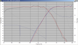
Initally I had the speaker curves matching the target curves quite well, but after tweaking (manually) for better reverse null these came off a bit on the knees of the curves. Still +/- 1db between around 160Hz and 12Khz is not bad!
Try the below with your frd and zma files in box sim and see how it looks.
There's room for improvement, but I think this would probably work ok, and has the advantage that it is a simple network. Note that I have not really looked at distortion profile of the tweeter, I'm assuming with it's low resonant frequency it should handle the relatively low crossover point.
Tony.
1.8mH I used a janzten p-core as reference, DCR 0.135 ohms.
400mH I used a jantzen air core 20ga DCR 0.43 ohms (note you need this dcr to help the phase to line up a bit better).
Target for the LP was 3rd order butterworth 2.2K at 84db
Target for the HP was 3rd order butterworth 2.8K at 84db
Initally I had the speaker curves matching the target curves quite well, but after tweaking (manually) for better reverse null these came off a bit on the knees of the curves. Still +/- 1db between around 160Hz and 12Khz is not bad!
Try the below with your frd and zma files in box sim and see how it looks.
There's room for improvement, but I think this would probably work ok, and has the advantage that it is a simple network. Note that I have not really looked at distortion profile of the tweeter, I'm assuming with it's low resonant frequency it should handle the relatively low crossover point.
Tony.
Attachments

Good phase matching doesn't require acoustic centre matching but may result in assymetrical filters.I can not quite understand the phase plot in post #82. It appears to me the SEO of the woofer is too far behind and should be reduced by about 15 mm in order to make the prediction more accurate.
The chaotic nature of cone breakup casts a doubt on that region of the shown data so that might have 'helped'.
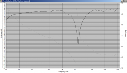
This is what the phase looks like with Tony's design:
Thanks for all the help,
Jeremy.
An externally hosted image should be here but it was not working when we last tested it.
Thanks for all the help,
Jeremy.
Hi Jeremy, a little different but not wildly (which is good). I just realised that I think you have 2mm offset (same direction as woofer) on the tweeter too. I put that into speaker workshop and the phase shifts over a bit more like what you show above, although in SW the phase matching is then quite good from about 2.2K through about 3K and the reverse null is much deeper (down to about 46db)...
How does the frequency response look? Also what about off axis (I think boxsim can simulate that correct?)
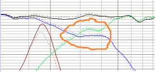
The main part I didn't like about your previous graph was the circled part. each driver flattens out for a while before continuing on down. The slope should be more or less constant, whilst the shown response of each driver may sum flat on axis I have my doubts about how it would sound. I would also like to see a reverse null of the response of that version. I suspect it would not be symmetrical. off axis may also be a bit ugly...
Anyway hopefully what I've posted gives you some food for thought 🙂
Tony.
How does the frequency response look? Also what about off axis (I think boxsim can simulate that correct?)
The main part I didn't like about your previous graph was the circled part. each driver flattens out for a while before continuing on down. The slope should be more or less constant, whilst the shown response of each driver may sum flat on axis I have my doubts about how it would sound. I would also like to see a reverse null of the response of that version. I suspect it would not be symmetrical. off axis may also be a bit ugly...
Anyway hopefully what I've posted gives you some food for thought 🙂
Tony.
Attachments
Cool someone else has done a build with the D5G's. How did you like the sound Wolf?
It seems like everyone has been leaning towards the tang band so it looks like i will be using that driver. All i have to do now is learn how to use boxsim...
Just now saw this....
The D5G's have a warmth to them that is pleasant. In the box I used, it's small volume allowed the 5s to only respond to about 45-50Hz before rolloff, but I wanted the small box woofer, and this is one of about 6 that will play high enough to meet a tweeter and go reasonably low in that volume. FWIW, the driver complement really suits each other in terms of tonality and resolution. Neither is overly analytical, and both are quite smooth. This project was really easy on the ears no matter the music, but it does crave power and falls short on realism at times. I'm actually still not positive I have the top-end as I want it. I tamed the sibilance, but now they seem a bit dead to me on top.
It was an interesting design approach from the start to challenge my wood working, and paired some drivers that not everyone would attempt. It does sound pretty good.
Later,
Wolf
Thanks for the reply Wolf.
I already have plans for what I'm gonna do with my D5g's but that'll have to wait till after I've finished this project. 🙂
Now back to Tony and Allenb,
So the main problems with my phase so far is that the gradient on the right is not matching for the drivers? I still don't really understand what the graph means. Something to do with unit circle diagrams?
What would good phase be? +-10 degrees all the way along?
So are there any ways to steepen the tweeters gradient on the right?
Reverse null? (Polarity?)
So many questions 😛
The optimiser seems to flatten the response for the drivers at the crossover point for some reason. I was wondering if that would effect the sound.
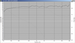
Frequency response for Tony's design:
Thanks,
Jeremy
I already have plans for what I'm gonna do with my D5g's but that'll have to wait till after I've finished this project. 🙂
Now back to Tony and Allenb,
So the main problems with my phase so far is that the gradient on the right is not matching for the drivers? I still don't really understand what the graph means. Something to do with unit circle diagrams?
What would good phase be? +-10 degrees all the way along?
So are there any ways to steepen the tweeters gradient on the right?
Reverse null? (Polarity?)
So many questions 😛
The optimiser seems to flatten the response for the drivers at the crossover point for some reason. I was wondering if that would effect the sound.
Frequency response for Tony's design:
An externally hosted image should be here but it was not working when we last tested it.
Thanks,
Jeremy
Hi Jeremy, phase is just simply how well aligned the wave forms from each speaker are at a particular frequency and point in space. phase is measured in degrees with 360 degrees representing one ful cycle of a Sine wave. I saw an excellent annimation once of a sine wave with a circle showing the phase angle rotation, unfortunately I can't find it.
two waves that are in phase will add together. Two waves that are 180 degrees out of phase will subtract from each other. The reverse null is a test where one driver is connected in reverse polarity, if you get a deep null (at the crossover design frequency) then it shows that both drivers are in good phase alignment at the crossover point. If the null is relatively symetrical, then the phase matching either side of the crossover point is also good.
The example I posted, I would personally be quite happy with from a phase perspective. It may be possible to improve it but it is unlikely to make much of a difference in reality. It probably needs a little tweaking for you actual driver offsets. But I would do this by making small changes to one component at a time and seeing what the effect is, not with the optimizer. What you ideally want is the phase lines to line up exactly at the actual crossover point and for some distance either side. The further away from the crossover point either way, the less important the phase matching is because the drivers not contributing as much.
Resistance in series with the shunt capacitor and in series with the shunt coil can be used to vary the phase (but will also change the response), changes in values of coils and caps will also have an effect, as will adding or subtracting an order in the filter (though this is generally a much bigger change).
Tony.
yes this one Comparing Circular and Sinusoidal Motion from there is similar to what I had seen 🙂
Tony.
Tony.
I also noticed that. I would place the notch at the breakup frequency instead. I would try replacing a 1uF to the 0.1uF, and adding also a resistor (RC in series, both in parallel to the main 1.4mH coil). The value of the cap sets the frequency of the notch. the resistor varies the depth.
Ralf
Ralf
I found the 3.16 frequency factor curious, assumed it was a coincidence.I would try replacing a 1uF to the 0.1uF,
One way to begin to flay an optimiser into shape could be to get it to do each driver separately to a target response. The reason it would be even better with the notch filter right on the breakup is that this region could then simply be taken a couple more dB down from that target.
- Status
- Not open for further replies.
- Home
- Loudspeakers
- Multi-Way
- Advice on bookshelf speaker build