Ah yes, you also need the spltools then. SPL Tools the splviewer allows you to "normalize" the response. It will extrapolate down to 20Hz and up to 20Khz if your measurement doesn't extend that far. The lower range is more important for extracting the phase.
It unfortunately doesn't let you normalize impedance files, if the worst comes to the worst you can add in some rows in excell for the zma to pad it out. Just take a look at another zma for a similar tweeter to see what the data points are.
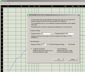
I don't use the default settings attached is a screen shot of what I use.
Tony.
It unfortunately doesn't let you normalize impedance files, if the worst comes to the worst you can add in some rows in excell for the zma to pad it out. Just take a look at another zma for a similar tweeter to see what the data points are.
I don't use the default settings attached is a screen shot of what I use.
Tony.
Attachments
Last edited:
Every time I open the SplTrace app I get this error:
Has this happened to you?
Jeremy.
An externally hosted image should be here but it was not working when we last tested it.
Has this happened to you?
Jeremy.
I bet you are running a very high resolution screen? I think it has a wobbly if the screen res is too high.. should work fine with 1280 X 1024 but higher than that I think it craps out... or that is my recollection.. Is it only when you try and load the file? I think I just resized the window and it was fine..
It's actually splview you need to do the normalization though.
Tony.
It's actually splview you need to do the normalization though.
Tony.
Nothing seems to run properly on my ultra-wide 😛.
Anyway splview seems to work when not running fullscreen.
Jeremy.
Anyway splview seems to work when not running fullscreen.
Jeremy.
Okay I have imported the zma's and frd's into boxsim.
This is what the phase is like now.
Jeremy.
An externally hosted image should be here but it was not working when we last tested it.
This is what the phase is like now.
Jeremy.
I was mucking around with the SEO and have got the gradients of the phase to match.
This was with 10 mm for the woofer and 15 mm for the tweeter.
So what does this SEO actually mean? 10 mm recess?
Thanks,
Jeremy.
This was with 10 mm for the woofer and 15 mm for the tweeter.
An externally hosted image should be here but it was not working when we last tested it.
An externally hosted image should be here but it was not working when we last tested it.
An externally hosted image should be here but it was not working when we last tested it.
So what does this SEO actually mean? 10 mm recess?
Thanks,
Jeremy.
I'll leave that one for Steve to answer, as I'm not familiar with boxsim. I think though that you should probably be choosing one driver as the 0 offset and having the other one + or - so many mm from that reference.
This is the tricky bit IMO when doing sims with manufacturers data. you have to take a guestimate as to where the relative accoustic centres of the drivers are. For tweeters (unless they are horn loaded) it is usually pretty close to the baffle, for mids/woofers it will be behind the baffle. The deeper the cone of the driver the further behind it will be. Any manufacturers drawings will probably be the best bet for taking a guess. anything short of real measurements on the baffle will not be 100% accurate, so near enough is good enough in this case and I wouldn't spend an inordinate amount of time getting the phase matching perfect, as it will likely be different in the real implementation. If you get a crossover though that performs well + or - a few mm in offset then you should be set 🙂
Tony.
So what does this SEO actually mean? 10 mm recess?
Thanks,
Jeremy.
SEO is acoustic center offset. Boxsim suggests positive
values for the center being behind the baffle.
Hey Guys,
Does this mean the tweeter voice coil has be 15 mm behind the baffle and the woofer voice coil 10 mm behind the baffle?
I'm still confused 😛
Thanks, Jeremy
Does this mean the tweeter voice coil has be 15 mm behind the baffle and the woofer voice coil 10 mm behind the baffle?
I'm still confused 😛
Thanks, Jeremy
hmmm I went back and see that Steve said that usually tweeters are set at 15mm behind the baffle and woofers at 30mm behind the baffle.
The "acoustic center" of a driver is a nominal term to represent the sounds origin. what happens is that the path length from each speaker to the listeners ear is slightly different, resulting in the signals being (somewhat) out of phase.
The crossover itself can be used to compensate for this difference in phase. ideally you want the phase aligned at the crossover point and a reasonable distance either side.
The offsets you are putting in are supposed to represent the actual physical implementation, and you then need to try and get your crossover values to align the phase.
This of course assumes you are not instead trying to set your baffle up to have the drivers acoustic centers coinciding (sloped baffle, stepped baffle, tweeter with waveguide etc).
So what you should put into the SEO param is what the actual realization of the drivers will be, not what makes it have the best phase 😉
Tony.
Last edited:
I guess I'm gonna have to wait till the drivers arrive so I can do some measurements. The dimensions on tang bands website do not include the depth of the cone ( I'm guessing that's where the sound origin is).
Thanks, Jeremy.
Thanks, Jeremy.
You are correct.I guess I'm gonna have to wait till the drivers arrive so I can do some measurements. The dimensions on tang bands website do not include the depth of the cone ( I'm guessing that's where the sound origin is).
Thanks, Jeremy.
Hi Guys
The drivers finally arrived 😛
The SEO is around 35 mm for the drivers and 2 mm for the tweeters.
I have been having problems with getting the phase right. When I try a crossover point around 3.5 KHz, Boxsim optimises it down to 2.4 KHz, and when I try a crossover point around 5 KHz, Boxsim optimises it up to 6 KHz.
I can only get the drivers in phase around these two frequencies.
I have tried to manually optimise it but I can't seem to get it right either. I have been trying different types of crossovers as-well but none seem to work.
Any tips?
I'm probably doing something wrong haha
Thanks, Jeremy
Last edited:
try playing with some resistance in series with the shunt cap on the woofer circuit. Also it may help to drop back to 2nd order filter on the woofer depending on just how much your phase difference is. You can often get the same acoustic response using a 2nd order electrical as you can with a third order electrical. I usually end up with 2nd order on the woofer, and third order on the tweeter, for a fourth order target accoustic slope.
Tony.
Tony.
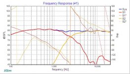
After many hours of trial and error I have finally designed something decent. (I think)
Crossed at around 2.9 KHz
Is the phase matched good enough?
I've had the judge phase (In results thingy) bellow 0.1 before but that was at a much lower frequency.
Thanks, Jeremy
Crossed at around 2.9 KHz
An externally hosted image should be here but it was not working when we last tested it.
An externally hosted image should be here but it was not working when we last tested it.
An externally hosted image should be here but it was not working when we last tested it.
Is the phase matched good enough?
I've had the judge phase (In results thingy) bellow 0.1 before but that was at a much lower frequency.
Thanks, Jeremy
Looking at how the green line goes above the sum, the phase between drivers is off. I don't know boxsim, so I don't know if it is possible to have such a graph, but you should look at the phase of the two drivers with the crossover, something like the picture attached.
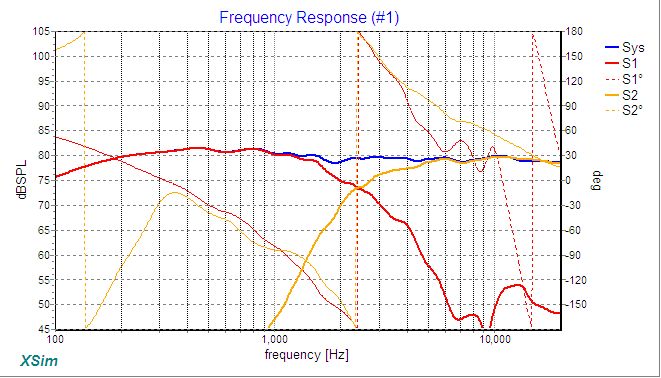
Anyway I would tame the bump of the woofer (3-5KHz), this can be accomplished by a CR circuit in parallel to the main coil. For an example have a look here: Studio-101
Another point of attention: optimizers are a good thing, but you need to have a look of the values of the components: I think you'll have a hard time to find all the values needed, especially a 1nF audio grade cap.
Ralf
Attachments
Hi Jeremy I think what you had before was closer to what Ralf is saying. It looks like in an attempt to get phase matching your driver acoustic slopes have suffered.
I'd be more inclined to get slopes matching a good 4th order acoustic rolloff with non-optimal phase matching than I would to have good phase matching at the crossover point but lumpy FR in either driver in the crossover region.
Tony.
I'd be more inclined to get slopes matching a good 4th order acoustic rolloff with non-optimal phase matching than I would to have good phase matching at the crossover point but lumpy FR in either driver in the crossover region.
Tony.
The response on axis would be the main concern when fixing phase. The benefit of precise phase matching tends to be limited by the imperfections of a practical crossover. A phase difference could even be used to advantage with this.
[Edit: Hi Tony, you posted this an hour before me, time flies when you're watching a movie and posting at the same time 🙂]
[Edit: Hi Tony, you posted this an hour before me, time flies when you're watching a movie and posting at the same time 🙂]
Last edited:
Woops forgot to attach the phase graph 😛
An externally hosted image should be here but it was not working when we last tested it.
- Status
- Not open for further replies.
- Home
- Loudspeakers
- Multi-Way
- Advice on bookshelf speaker build