Steve, yes I tried taking out the caps altogether and it worked just the same, only problem was that the impedance dropped to around 1/2 what it would be without the notch since it was just (effectively) a frequency dependent resistor in parallel with the woofer 🙂 That was the main reason I dropped back to basics, and was actually a little surprised at just how well it went! It's not perfect but it's certainly a good starting point!
The 2.4Khz was just where it seemed to work well, I started at 2.2K and worked my way up. 2.2K because that was pretty much where Jeremy was aiming originally.
Tony.
The 2.4Khz was just where it seemed to work well, I started at 2.2K and worked my way up. 2.2K because that was pretty much where Jeremy was aiming originally.
Tony.
I have finally designed a crossover that does not have overly large components and is decently flat.
How does this look to you guys?
I have changed the dimensions, volume (16L 55 Hz) and chamfer for the enclosure:
Jeremy.
An externally hosted image should be here but it was not working when we last tested it.
An externally hosted image should be here but it was not working when we last tested it.
How does this look to you guys?
I have changed the dimensions, volume (16L 55 Hz) and chamfer for the enclosure:
An externally hosted image should be here but it was not working when we last tested it.
Jeremy.
Jeremy, we are in the business of putting old heads on young shoulders here. To get you through this to a good result. 🙂
Tang Band W5-704D 5-1/4" Woofer
That's a reflex driver with a Vas of 11L and a Qts of 0.38. So 11L or smaller it is! With a smallish port.
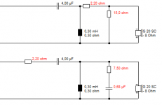
Your filter is crossing over too low. We can do a 3.5kHz XO here on second order IMO. I really don't think 5R and 0.2mH is useful here. Lose it. It's an old trick to give the shunt capacitor on the bass some resistance where bass inductance Le plays a part. It aligns phase and slopes nicely.
Give Boxsim the below circuit to optimise for your drivers, and watch phase alignment too, which matters for the drivers to sound integrated. My own sim is for a similar paper driver in closed box, so don't expect the result to be exactly the same.
FWIW, Boxsim usually calculates the bass up on stands in the middle of the room. Diffraction at baffle. In practise wall effects will boost the bass, so don't mind a slight upwards slope on the bass.
Tang Band W5-704D 5-1/4" Woofer
That's a reflex driver with a Vas of 11L and a Qts of 0.38. So 11L or smaller it is! With a smallish port.
Your filter is crossing over too low. We can do a 3.5kHz XO here on second order IMO. I really don't think 5R and 0.2mH is useful here. Lose it. It's an old trick to give the shunt capacitor on the bass some resistance where bass inductance Le plays a part. It aligns phase and slopes nicely.
Give Boxsim the below circuit to optimise for your drivers, and watch phase alignment too, which matters for the drivers to sound integrated. My own sim is for a similar paper driver in closed box, so don't expect the result to be exactly the same.
FWIW, Boxsim usually calculates the bass up on stands in the middle of the room. Diffraction at baffle. In practise wall effects will boost the bass, so don't mind a slight upwards slope on the bass.
Attachments

Last edited:
Hey Steve
Just wondering why the volume has to be smaller than the vas (and what the vas actually is haha). Also I am using Zaphs measurements which say the vas is 7.8L and the qt is 0.62.
I have simulated the crossover you have suggested and optimised it to a relatively flat response. However, I cannot seem to get the phase in line and the optimiser seems to make it worse.
I have also changed the volume to 11 litres for this sim.
Thanks Jeremy
Just wondering why the volume has to be smaller than the vas (and what the vas actually is haha). Also I am using Zaphs measurements which say the vas is 7.8L and the qt is 0.62.
I have simulated the crossover you have suggested and optimised it to a relatively flat response. However, I cannot seem to get the phase in line and the optimiser seems to make it worse.
An externally hosted image should be here but it was not working when we last tested it.
An externally hosted image should be here but it was not working when we last tested it.
An externally hosted image should be here but it was not working when we last tested it.
I have also changed the volume to 11 litres for this sim.
Thanks Jeremy
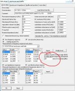
hmmm I used the manufacturers T/S params in my sim. qts is 0.38. I would not finalize any plans without doing your own T/S measurements. 0.62 compared to 0.38 indicates potentially faulty drivers, or something went wrong with the measurements, I'd be inclined to trust the manufacturers T/S params more than Zaph's in this scenario.
I modeled vented at 11L and I think 54Hz tuning frequency, is the above with sealed 11L?
Tony.
I modeled vented at 11L and I think 54Hz tuning frequency, is the above with sealed 11L?
Tony.
Should I be changing the zma and frd files as well?
The last sim was with a ported 11L enclosure tuned to 50 Hz.
Thanks, Jeremy
The last sim was with a ported 11L enclosure tuned to 50 Hz.
Thanks, Jeremy
I just checked Zaphs T/S params, it's Qt of 0.48 which is different but not as different at 0.62 😀
I can see why you had Volume of 16L that's much more suitable based on those params. I just tried 16L and somewhere around the 47 Hz mark looks good. Zaph's measurements are within about 25% of the manufacturers which is probably within the variation you could expect to get.
Zaph's measurements are more desirable than the Manufacturers ones... They result in a bigger volume for the box. I think go with them, if it turns out the driver is closer to the manufacturers specs, making a box smaller is easy (just glue some blocks of wood in the bottom to reduce the volume 🙂 )
So I'd stick with Zaph's measurements and also with your 16L box size for now. It's relatively easy to do T/S measurements, provided you have a sound card with line in and line out, you can make a simple jig for a few dollars Cables (the impedance jig) and use a program like REW or ARTA to measure the impedance curve. The trickiest bit is the VAS, and you either get an accurate scale (accurate to about 0.1g) and do added mas, or make a small test box and do delta compliance. both cases just a second run of the impedance sweep either with known mass added to the cone, or speaker in the test box of known volume.
Using your own impedance measurements in your own box (even if you still use manufacturer's data for SPL) will give the best results for your crossover simulation, and it is probably the easiest measurement you can do yourself 🙂
Tony.
Where are you getting these t/s parameters from?
I got mine from here:http://www.zaphaudio.com/oldversions/Tangband-W5-704S-TS.gif
I got mine from here:http://www.zaphaudio.com/oldversions/Tangband-W5-704S-TS.gif
A Qts of 0.38 for reflex is just one of those magic values which sticks in the mind. Like Qts 0.5 for closed box. The optimal box is just the Vas. 😎
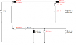
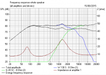
There's something seriously wrong with the phase for the bass here given the tidy slopes. Possibly the acoustic centre (aka point of sound origin, SEO) is set wrong. It should be about 30mm behind the baffle IMO for a 5". Tweeters are usually about 15mm behind the baffle. You should always look at impedance too, lest it dips below 4 ohms which the amp won't like. That 13.8R series resistor is one way of doing things with a tweeter, and can sound good, but not the only way.
An externally hosted image should be here but it was not working when we last tested it.
There's something seriously wrong with the phase for the bass here given the tidy slopes. Possibly the acoustic centre (aka point of sound origin, SEO) is set wrong. It should be about 30mm behind the baffle IMO for a 5". Tweeters are usually about 15mm behind the baffle. You should always look at impedance too, lest it dips below 4 ohms which the amp won't like. That 13.8R series resistor is one way of doing things with a tweeter, and can sound good, but not the only way.
Attachments
Last edited:
So I have been using the wrong T/S parameters this whole time 😛
It took me a matter of minutes to design this crossover (modelled of Steves)
It is now crossed at around 3KHz in a 16 (should this still be smaller) litre box tuned to 50Hz. I am assuming the slope from 50 to 200 Hz will get filled in by wall effects as Steve has suggested.
What do you guys think?
Also, should I be using air cores for the 1.8 mH inductor or is a solid core fine?
Thanks, Jeremy.
It took me a matter of minutes to design this crossover (modelled of Steves)
An externally hosted image should be here but it was not working when we last tested it.
An externally hosted image should be here but it was not working when we last tested it.
An externally hosted image should be here but it was not working when we last tested it.
It is now crossed at around 3KHz in a 16 (should this still be smaller) litre box tuned to 50Hz. I am assuming the slope from 50 to 200 Hz will get filled in by wall effects as Steve has suggested.
What do you guys think?
Also, should I be using air cores for the 1.8 mH inductor or is a solid core fine?
Thanks, Jeremy.
This is looking about right. Phase is still wrong though. Have a look and a play with SEO. It should all fall into place then. Also then try some shunt resistance with the bass capacitor. Air cores are more expensive than bass ferrites, but theoretically sound better. IDK. LOL.
Attachments
Last edited:
I only just noticed your reply Steve 🙂
I have changed the volume to 12 litres (vas is 12L from Zaphs measurements)
How would I change the acoustic centre thing you were talking about in boxsim?
Thanks, Jeremy
I have changed the volume to 12 litres (vas is 12L from Zaphs measurements)
An externally hosted image should be here but it was not working when we last tested it.
How would I change the acoustic centre thing you were talking about in boxsim?
Thanks, Jeremy
Oh you replied again lol.
I'll muck around with that sound origin thing.
What should the phase graph look like?
Jeremy
I'll muck around with that sound origin thing.
What should the phase graph look like?
Jeremy
Ah, Jeremy, I like the live stuff! 😀
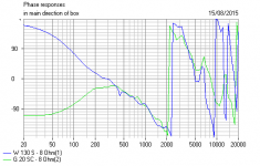
As you move a speaker's acoustic centre back, the phase slope goes down steeper.
So we ought to be getting something like the below that I quoted earlier. The drivers then reinforce each other nicely for a -6dB phase aligned crossover, aka Linkwitz-Riley. It gives a detailed and integrated sound if you sit in the sweet spot horizontally. It's hard to tell that you have two drivers if you get it right.
Attachments
Moving the acoustic centre back doesn't seem to do anything to the phase graph.
Does this mean there's something wrong with the crossover?
Jeremy.
Does this mean there's something wrong with the crossover?
Jeremy.
Hmm, that IS strange. 😕
Sounds like you have imported FRD and ZMA files into Boxsim. But there's more to it than that. Depends on how the measurements were taken, for one thing. Like baffle size. And also on some other parameters than pure FR and impedance and phase.
Probably time to take a break, in best tradition when knocking your head against a brick wall. 😀
Polycones usually get simpler filters than paper cones. Because they are smoother frequency response by nature.
You MIGHT just set up another project with a Visaton W130S, and try and figure out what is going wrong here. TBH, I don't know what the issue is. But, TBH, I don't think you are far off the final filter.
Last edited:
For some reason the spreadsheet crashes when I try to extract the tweeters frd. I have extracted all the other files without any problem.
Does the file have to be in a specific format (20 Hz to 20 KHz)?
The frd I have for the tweeter starts from 300 Hz.
Jeremy.
Does the file have to be in a specific format (20 Hz to 20 KHz)?
The frd I have for the tweeter starts from 300 Hz.
Jeremy.
- Status
- Not open for further replies.
- Home
- Loudspeakers
- Multi-Way
- Advice on bookshelf speaker build