For I2S output the crystals provide the SAI clock for the MCU which generates the I2S signals (BCK, SD and LRCK). MCK out is divided from the crystal . For I2S input the board acts as a slave.
Define relatively high and especially the audibility.
With STM32F7 I believe this to be the best (if not the only) arrangement. Besides I'm using ES9038 and AK4137 chips which both have ASRCs so jitter is not a concern.
With STM32F7 I believe this to be the best (if not the only) arrangement. Besides I'm using ES9038 and AK4137 chips which both have ASRCs so jitter is not a concern.
"...both have ASRCs so jitter is not a concern."
Not a problem for most measurement purposes. Maybe still a problem for high-end listening use. In particular, I have used ESS chips and AK4137. Despite having internal ASRCs both sound better with lower incoming jitter (for ESS parts, particularly if DPLL_Bandwith is configured as ESS recommends). One may recall there is still what some might call a PPLL involved (poly-phase locked loop), and it has corner frequency for jitter suppression.
Not a problem for most measurement purposes. Maybe still a problem for high-end listening use. In particular, I have used ESS chips and AK4137. Despite having internal ASRCs both sound better with lower incoming jitter (for ESS parts, particularly if DPLL_Bandwith is configured as ESS recommends). One may recall there is still what some might call a PPLL involved (poly-phase locked loop), and it has corner frequency for jitter suppression.
Maybe you should show the jitter measurement (or close-in phase noise) of your high-end stuff.
It would be interesting if we could easily do that. A couple of guys say they are working on an upconverter to measure with a Time Pod; we'll see if it happens. In the meantime putting clocks on the dac side of isolators (along with reclocking of jittered I2S signals) is already doable and helps reduce audible jitter at low-ish cost, so why not do it?
Last edited:
I just prefer to have the low jitter oscillator close to the ADC and DAC. This way jitter is kept at a minimum and there is no need to reduce the jitter.
I don't have the jitter measurements available right now, but as I remember it, the jitter from the isolators was in the order of 1 ns.
I don't have the jitter measurements available right now, but as I remember it, the jitter from the isolators was in the order of 1 ns.
The I2S isolators I'm using have 250ps jitter according to the datasheet. And since the ADC is the I2S master it will have a separate oscillator.
It would be interesting if we could easily do that. A couple of guys say they are working on an upconverter to measure with a Time Pod; we'll see if it happens. In the meantime putting clocks on the dac side of isolators (along with reclocking of jittered I2S signals) is already doable and helps reduce audible jitter at low-ish cost, so why not do it?
I already explained the reasons for having the clocks at the USB side in this case. Maybe you have trouble understanding my explanation?
I just prefer to have the low jitter oscillator close to the ADC and DAC. This way jitter is kept at a minimum and there is no need to reduce the jitter.
I don't have the jitter measurements available right now, but as I remember it, the jitter from the isolators was in the order of 1 ns.
Maybe you can enlighten us with the jitter measurements of you RTX stuff. We can then compare how much better results you have obtained.
Maybe you should show the jitter measurement (or close-in phase noise) of your high-end stuff.
I am on that matter, without up converting 😀
I just prefer to have the low jitter oscillator close to the ADC and DAC. This way jitter is kept at a minimum and there is no need to reduce the jitter.
I don't have the jitter measurements available right now, but as I remember it, the jitter from the isolators was in the order of 1 ns.
Yes, Jens first USBStreamer add-on module with isolation and master clock feeding to the USBStreamer (trough isolation modules), the final RT6001 with own design.
If you really like to go ultimate and flexible as for
256 x 44.1/48kHz AKM ADC/DAC
512 x 44.1/48kHz most used for AKM ADC/DAC
1024 44.1/48kHz AKM / ESS
Master clock (as crappy oscillator or ultimated using an OCXO) then to a clock distribution module with various output as one to your USB I/O module...
Would be the yellow on the egg 🙄

Hp
bohrok2610: The problems you described, at least as far as I could tell, are already solved in a popular commercial product (I2SoverUSB). Have you looked at one to see how they did it?
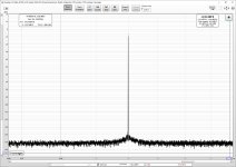
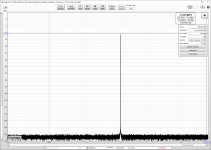
So far I don't see any problems with my design. The jtest measurements are fine.
Besides I2SOverUSB does not have I2S input which is actually the reason I created this. And last time I checked this site was DIYaudio (as in Do-it-yourself). Not buy-yourself-cheap-chinese (or whatever)-stuff-and-tweak-them-to-death.
And to clarify: I'm not selling or planning to sell anything audio related. I have designed this USBI2S bridge for only my private use.
I have designed this USBI2S bridge for only my private use.
That tells & explains all about 😱
"...both have ASRCs so jitter is not a concern."
Not a problem for most measurement purposes. Maybe still a problem for high-end listening use. In particular, I have used ESS chips and AK4137. Despite having internal ASRCs both sound better with lower incoming jitter (for ESS parts, particularly if DPLL_Bandwith is configured as ESS recommends). One may recall there is still what some might call a PPLL involved (poly-phase locked loop), and it has corner frequency for jitter suppression.
Urgh. You can't resist, don't you?
That tells & explains all about 😱
I'm not sure how to interprete this. Anyhow if you (or anybody else) have some suggestions on how to improve the audio clock distribution of STM32F7 SAI based implementation I'm more than happy to discuss further.
As I wrote, I don't have the jitter measurements on the isolators available right now.Maybe you can enlighten us with the jitter measurements of you RTX stuff. We can then compare how much better results you have obtained.
I just made a jtest in REW on the RTX6001, with a loop back connection. I used settings very similar to yours to make it easier to compare (FFT lenght, window, averaging etc.). The result is attached.
I was merely trying to give my advice on what I think is the best clock concept for a USB interface. Feel free to disagree and design it the way you want.I'm not sure how to interprete this. Anyhow if you (or anybody else) have some suggestions on how to improve the audio clock distribution of STM32F7 SAI based implementation I'm more than happy to discuss further.
Attachments
- Home
- Design & Build
- Equipment & Tools
- ADCs and DACs for audio instrumentation applications