I have not tested FS, but for the HS this works fine:
EP-OUT: bInterval=only 1-4, not more (documented by MS)
sync EP-IN: bInterval= only 4 (I think it's even mentioned in MS docs)
feedback value - average number of samples per packet, not per uframe. So for EP OUT bInterval=4 the number corresponds to 1ms, for bInterval=1 to 125us (1/8th of the number). The linux UAC2 driver identifies the corresponding timeframe automatically, windows UAC2 just ignores the "wrong" feedback value and makes no changes in packet size (BTW just like OSX).
Windows UAC2 accepts bInterval=1 for the sync FB endpoint (also documented here: _USBD_PIPE_INFORMATION (usb.h) - Windows drivers | Microsoft Docs). But as I mentioned sending FB every SOF does not appear to work even though I have bInterval=1. Other than that I have no issues with the sync FB. No buffer overruns or underruns.
Well, that doc describes endpoints in general. I am saying what's tested to work OK and is honored by the windows driver. But it's good to learn other options work too.
Another minor quirk about Windows UAC2 is that the min and max allowed sync FB values are oddly not symmetric regarding sampling rates that are multiples of 44.1kHz.
I do not know exactly what you mean by "regarding sampling rates that are multiples of 44.1kHz". Sync FB range is typically not symmetrical. Slowing clocks is never a problem (just sending fewer samples), while faster requires reserved margin in the max packet size, eating available bandwidth for other transmissions. Real-world requirements are usually very modest, typically a few audio frames is enough (1/1024 of samplerate means a very imprecise clock). The worst scenarios I have seen differ by just a few Hz for 48kHz, +1 audio frame would be 48Hz diffference at worst case of full 1024 packet which is quite a large deviation.
Honestly, I do not see how this could present a problem for an implementer.
Honestly, I do not see how this could present a problem for an implementer.
For 44.1kHz the minimum fb value is 0x0005000 and max is 0x0006000 (i.e. asymmetric). For 48kHz the min is 0x0005000 and max is 0x0007000 (i.e. symmetric). Same with multiples of 44.1k and 48k.
Of course this is not a problem for the implementer once you find this out but to me it really does not make any sense to make these sample rate specific. Like I said these are just minor quirks. However there really should be no reason to allow incorrect descriptor to crash the whole computer. That is just really bad design.
Of course this is not a problem for the implementer once you find this out but to me it really does not make any sense to make these sample rate specific. Like I said these are just minor quirks. However there really should be no reason to allow incorrect descriptor to crash the whole computer. That is just really bad design.
That range is HUGE, never to be used in practice. IMO they just opted for some simple to remember limits.
That crash was ugly, lame coding and lack of testing. Probably Thesycon should bear the blame. OTOH - do you want to bother with paid licenses for an ASIO driver instead? 🙂
That crash was ugly, lame coding and lack of testing. Probably Thesycon should bear the blame. OTOH - do you want to bother with paid licenses for an ASIO driver instead? 🙂
IVX can I ask you what level of performance you get with the ES9822 without any THD compensation? In terms of THD?
IVX can I ask you what level of performance you get with the ES9822 without any THD compensation? In terms of THD?
@-.5dbfs 3rd at -120-125db, 2nd not sure close to -135db I think because the compensation-K2 usually within +/-2, when 3rd compensation-K3 +/-20 to get -132-138db level. Samples with low compensated 3rd, like -136-138db, has that level floats, hence better to calibrate that when sample for sure warmed up and settled.
Thanks IVX that gives me an idea of what to shoot for.
So I figured it would make sense to have a play with my AK4499s to get them performing up to spec. My distortion was slightly higher than other measurements (over on audiosciencereview) had shown the chip to be capable of. Whether or not these were golden samples I don't know but I wanted to try to improve things.
The AK4499 datasheet does indeed show that the distortion rises a little as you approach 0dBfs, and I was seeing such a degradation, but a little more than you'd expect. I was still getting all distortion products below -120dB but I wanted to do better.
I already knew that the power supplies to the chip were important. The obvious thing to do would be to use something like 4x LT3042/45 for the Vref supplies and then 4x some other device for the secondary 5V supplies. But that's expensive and occupies a lot of board space. So I went for 2x LT3045 per chip. One for the left channels and one for the right channels. I figured the recommended RC filters on Vref would keep the power there clean and the other supplies wouldn't care much. So one LT3045 powered 2x Vref and 2x the secondary supplies.
Using a two layer board and having the LT3045s located on one side of the PCB meant a long PCB trace, meandering around the I/V stages, to get to one of the channels, whilst the regulator sat next to the other channel.
Measuring this produced -120dB+ at the channel the regulator was close to but this degraded down to -106dB for the other one. Still not bad but not good either. The solution to this was to bypass the meandering trace and solder a thick piece of wire from the regulator directly to the channel on the far side. Once done all channels performed identically. While a wire isn't pretty it's certainly effective and far cheaper than another LT3045 and saves on board space.
At the time I was happy with this performance as it was only slightly inferior to the eval board for the AK4499. They were using a 4 layer PCB and I only 2 so I figured a small concession was reasonable. Then I saw how other manufacturers had got significantly better performance than the eval board. As I working with the ES9822 and had some free time I figured it would be worthwhile trying to squeeze some additional performance out of my AK4499s. Why? To make it easier to assess the ES9822 and because it's nice.
I started playing around with other regulators, still on the same PCB mind you, but splitting off the supplies from the LT3045s, and isolating them, to see what made any kind of difference. Adding in an ADP7118 to power the secondary supplies, and leaving the LT3045 on the Vrefs, gave me the kind of improvement I wanted. So even though the Vref supplies have a big RC filter, with a very low corner frequency, they still benefit from having the secondary supplies split from them. I wasn't particularly thrilled at the idea of having some 7118s on wires so I thought why not try something else. Use one LT3045 for all the secondary supplies and one LT3045 for all the Vrefs. Lots of wires to hook things up to the right places but only wires and no new silicon and no new PCB. This also worked. So basically keep the two power domains separate and you're home dry. You don't appear to need separate regulators for each pin which my frugal nature definitely appreciates.
This is how it ended up looking.
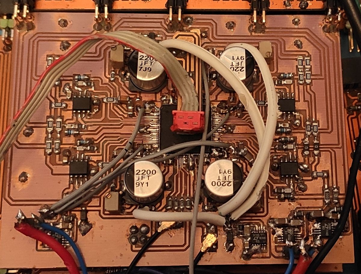
Not pretty but effective.
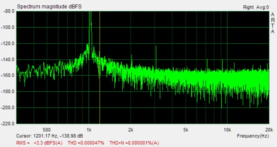
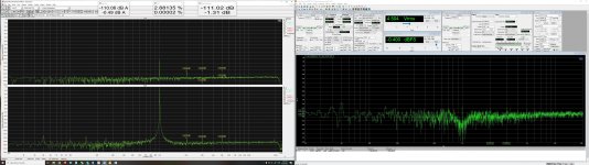
Dropping the output to -2dBfs lowers the distortion even further to around 0.000025%. Which is much better than I had before. Before I had to wind it back to -3dB just to see 0.00006%.
I have two AK4499 boards, one on top of the other, for dual mono. The measurement above is for mono-mode of one chip. After the I/V and RC filtering I have an OPA1622, in inverting configuration, as an output buffer and attenuator cutting the large signal swing of the I/V stage down to 4VRMS balanced. This is per channel of the AK4499 with the mono mode channel summation occurring after the OPA1622s. The measurement was taken after the OPA1622s.
Obviously I'm using an active Twin-T to make any kind of sense of the measurements at distortion levels this low. Using ARTAs frequency response compensation to apply a reverse of the notch to the FFT analysis and calculate the THD/THD+N figures correctly. Obviously I took great care to measure the depth of the notch otherwise the compensated THD/THD+N figures would be wildly inaccurate. No doubt there is some error involved as tuning two notches, for the balanced connection, isn't easy. But as the amount of attenuation the notch applies, to the 2nd and 3rd harmonics, is extremely small I'm fairly confident that the results are within a dB or two of where they should be. The ES9822 was the ADC used.
I/V Stage tuning.
Pushing distortion levels this low isn't easy and one of the biggest contributors can easily be the opamps. I had tried the ADA4898, at one point, and although it produced excellent results at 1kHz it really fell to pieces as frequency rose. Whether or not it disliked the large voltage swing, or capacitance over the I/V resistor, I do not know but it was not happy. Swapping in the OPA1612 made a big difference at high frequencies.
There really aren't that many opamps you can use for a low noise, high current, vanishingly low distortion application as syn08 has shown with his 38PRO implementation but the I/V capacitor can be critical to this.
Instead of the 360 ohm resistor that AKM recommend I had gone with a 390 ohm resistor. Why? 360 weren't cheaply available in the MELF resistors I wanted and a bit of extra voltage swing never really hurt either.
Now AKM had used a 180pF cap in combination with the 360 ohm so I figured I should be able to get away with slightly less for the same fc. Before I had used a value of 100p but I wanted to see if there was any real room for improvement. I decided to try using a 47p to load the I/V stage even less. Distortion was superbly low but the noise floor rose by a dB or 2. Prior to this I had tried the OPA1612 without any cap at all and the noise floor really shot up, by 10-20dB. This is why we need the cap otherwise the opamp can't handle the high frequency noise the DAC puts out. The faster the opamp the less capacitance you need, or if you were to use something slower, like the OPA1622, you'd need significantly more.
So 47p caused the noise floor to rise a little, not good, and the distortion was just as low as 100p. But was the noise floor with 100p as low as it could get? I decided to try a 470p just too see if this would make any difference. It did not. The noise floor with 470p was just as low as with the 100p but the distortion performance was significantly worse at 0dBfs. The third order shot up by an order of magnitude, not something I was happy with at all! So back in went the 100p and all was well again.
With the 470p distortion was superbly low up until around -10dB and then it began to creep up.
Whether or not this holds true for every op-amp you may wish to use I don't know. Or even if it holds true for different DACs also. But it would appear that you should definitely fine tune the I/V cap for the opamps you are using. Not too small that the noise floor increases but not too big that the opamp might kick up a fuss about driving it.
Syn08 I seem to recall a schematic you posted a while ago for your 38PRO showed rather large I/V caps? Maybe that was just for the OPA1622 and it required them. I figured that maybe using a tiny cap with the OPA1612 might be worth a shot.
It is also interesting to note that audiosciencereview have, somewhat, recently measured the Topping D90SE. This uses the 38PRO and achieves the best performance he's ever measured. What's interesting is that to achieve this Topping have used a bunch of OPA1612s for the I/V conversion. To my eyes it looks like they are using 16 opamps for the 8 channels inside the 38PRO, in parallel combinations, then summing all the outputs, to give them the noise and distortion figures necessary. To me this seems a little overkill just for distortion but it might be required for noise. Either way it's an interesting approach.
So I figured it would make sense to have a play with my AK4499s to get them performing up to spec. My distortion was slightly higher than other measurements (over on audiosciencereview) had shown the chip to be capable of. Whether or not these were golden samples I don't know but I wanted to try to improve things.
The AK4499 datasheet does indeed show that the distortion rises a little as you approach 0dBfs, and I was seeing such a degradation, but a little more than you'd expect. I was still getting all distortion products below -120dB but I wanted to do better.
I already knew that the power supplies to the chip were important. The obvious thing to do would be to use something like 4x LT3042/45 for the Vref supplies and then 4x some other device for the secondary 5V supplies. But that's expensive and occupies a lot of board space. So I went for 2x LT3045 per chip. One for the left channels and one for the right channels. I figured the recommended RC filters on Vref would keep the power there clean and the other supplies wouldn't care much. So one LT3045 powered 2x Vref and 2x the secondary supplies.
Using a two layer board and having the LT3045s located on one side of the PCB meant a long PCB trace, meandering around the I/V stages, to get to one of the channels, whilst the regulator sat next to the other channel.
Measuring this produced -120dB+ at the channel the regulator was close to but this degraded down to -106dB for the other one. Still not bad but not good either. The solution to this was to bypass the meandering trace and solder a thick piece of wire from the regulator directly to the channel on the far side. Once done all channels performed identically. While a wire isn't pretty it's certainly effective and far cheaper than another LT3045 and saves on board space.
At the time I was happy with this performance as it was only slightly inferior to the eval board for the AK4499. They were using a 4 layer PCB and I only 2 so I figured a small concession was reasonable. Then I saw how other manufacturers had got significantly better performance than the eval board. As I working with the ES9822 and had some free time I figured it would be worthwhile trying to squeeze some additional performance out of my AK4499s. Why? To make it easier to assess the ES9822 and because it's nice.
I started playing around with other regulators, still on the same PCB mind you, but splitting off the supplies from the LT3045s, and isolating them, to see what made any kind of difference. Adding in an ADP7118 to power the secondary supplies, and leaving the LT3045 on the Vrefs, gave me the kind of improvement I wanted. So even though the Vref supplies have a big RC filter, with a very low corner frequency, they still benefit from having the secondary supplies split from them. I wasn't particularly thrilled at the idea of having some 7118s on wires so I thought why not try something else. Use one LT3045 for all the secondary supplies and one LT3045 for all the Vrefs. Lots of wires to hook things up to the right places but only wires and no new silicon and no new PCB. This also worked. So basically keep the two power domains separate and you're home dry. You don't appear to need separate regulators for each pin which my frugal nature definitely appreciates.
This is how it ended up looking.
Not pretty but effective.
Dropping the output to -2dBfs lowers the distortion even further to around 0.000025%. Which is much better than I had before. Before I had to wind it back to -3dB just to see 0.00006%.
I have two AK4499 boards, one on top of the other, for dual mono. The measurement above is for mono-mode of one chip. After the I/V and RC filtering I have an OPA1622, in inverting configuration, as an output buffer and attenuator cutting the large signal swing of the I/V stage down to 4VRMS balanced. This is per channel of the AK4499 with the mono mode channel summation occurring after the OPA1622s. The measurement was taken after the OPA1622s.
Obviously I'm using an active Twin-T to make any kind of sense of the measurements at distortion levels this low. Using ARTAs frequency response compensation to apply a reverse of the notch to the FFT analysis and calculate the THD/THD+N figures correctly. Obviously I took great care to measure the depth of the notch otherwise the compensated THD/THD+N figures would be wildly inaccurate. No doubt there is some error involved as tuning two notches, for the balanced connection, isn't easy. But as the amount of attenuation the notch applies, to the 2nd and 3rd harmonics, is extremely small I'm fairly confident that the results are within a dB or two of where they should be. The ES9822 was the ADC used.
I/V Stage tuning.
Pushing distortion levels this low isn't easy and one of the biggest contributors can easily be the opamps. I had tried the ADA4898, at one point, and although it produced excellent results at 1kHz it really fell to pieces as frequency rose. Whether or not it disliked the large voltage swing, or capacitance over the I/V resistor, I do not know but it was not happy. Swapping in the OPA1612 made a big difference at high frequencies.
There really aren't that many opamps you can use for a low noise, high current, vanishingly low distortion application as syn08 has shown with his 38PRO implementation but the I/V capacitor can be critical to this.
Instead of the 360 ohm resistor that AKM recommend I had gone with a 390 ohm resistor. Why? 360 weren't cheaply available in the MELF resistors I wanted and a bit of extra voltage swing never really hurt either.
Now AKM had used a 180pF cap in combination with the 360 ohm so I figured I should be able to get away with slightly less for the same fc. Before I had used a value of 100p but I wanted to see if there was any real room for improvement. I decided to try using a 47p to load the I/V stage even less. Distortion was superbly low but the noise floor rose by a dB or 2. Prior to this I had tried the OPA1612 without any cap at all and the noise floor really shot up, by 10-20dB. This is why we need the cap otherwise the opamp can't handle the high frequency noise the DAC puts out. The faster the opamp the less capacitance you need, or if you were to use something slower, like the OPA1622, you'd need significantly more.
So 47p caused the noise floor to rise a little, not good, and the distortion was just as low as 100p. But was the noise floor with 100p as low as it could get? I decided to try a 470p just too see if this would make any difference. It did not. The noise floor with 470p was just as low as with the 100p but the distortion performance was significantly worse at 0dBfs. The third order shot up by an order of magnitude, not something I was happy with at all! So back in went the 100p and all was well again.
With the 470p distortion was superbly low up until around -10dB and then it began to creep up.
Whether or not this holds true for every op-amp you may wish to use I don't know. Or even if it holds true for different DACs also. But it would appear that you should definitely fine tune the I/V cap for the opamps you are using. Not too small that the noise floor increases but not too big that the opamp might kick up a fuss about driving it.
Syn08 I seem to recall a schematic you posted a while ago for your 38PRO showed rather large I/V caps? Maybe that was just for the OPA1622 and it required them. I figured that maybe using a tiny cap with the OPA1612 might be worth a shot.
It is also interesting to note that audiosciencereview have, somewhat, recently measured the Topping D90SE. This uses the 38PRO and achieves the best performance he's ever measured. What's interesting is that to achieve this Topping have used a bunch of OPA1612s for the I/V conversion. To my eyes it looks like they are using 16 opamps for the 8 channels inside the 38PRO, in parallel combinations, then summing all the outputs, to give them the noise and distortion figures necessary. To me this seems a little overkill just for distortion but it might be required for noise. Either way it's an interesting approach.
Attachments

5th element, do not forget to limit BW for the Arta's FFT(I make it with a fake mic freq. response) to make THD+N equal AP reading. A-waiting is not a good idea for THD+N.
BTW, OPA1656 is better as I/U in 10kHz vs AOP1612 + 100mA output, but a bit noisy.
PS: diyaudio.com believes that the .mic file is invalid and doesn't let me upload that. So I put here the txt which you can save as a BW20_20k.mic to use in Arta:
12 40 0
18 5 0
20 3 0
22 1 0
25 0 0
30 0 0
40 0 0
60 0 0
100 0 0
150 0 0
250 0 0
500 0 0
1000 0 0
2500 0 0
5000 0 0
10000 0 0
11000 0 0
15000 0 0
19000 2 0
20000 3 0
21000 4 0
24000 6 0
35000 40 0
60000 80 0
100000 100 0
OPA1656 is better as I/U in 10kHz vs AOP1612 + 100mA output, but a bit noisy.
Interesting conclusion, exactly opposite of what I get. At what output current? My measurements are showing the OPA1656 distortions increase very quickly over 40mA. And yes, it is rather noisy.
Over 40mA output, OPA1612 + BUF34 is the best, closely followed by the OPA1622.
We did measure ES9822 ADC with the APx555 output and got THD+N -122db@1k, that's actually quite close to what APx555 loopback shows. AP's gen always too noisy, for instance, DAC+LPF 1kHz as a sine source makes ADC reading THD+N -123db and less.
Attachments

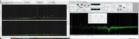
A short note regarding the lowest harmonics compensation. I didn't get a clue where is the reason but one of the samples I made, has an extremely low 3rd harmonic and it looks more or less steady in time. In fact, now the highest level has the 5th harmonic, and I even wish to add control for a 5th harmonic to the app, in the FW it is implemented already. Usually, 3rd harmonic stays on the level -133-135, whatever how long time you tried to compensate that, but this "MEGA GOLDEN SAMPLE" may show < -140db for both channels i.e. what actually AP analog gen has. SNR/DR performance looks 100% normal for all 6 samples.
The THD-N(minus noise ie bare THD) indicates 0.00002% steady. Unfortunately, all my samples are sent for testing or pending to be sent, and I can't exchange ES9822 to check if reason in the particular IC. I prepared that last sample by hand to make sure if all parts we got(many from spot suppliers due to the chaos around $ilicon) are good for the production run. Soon I'll test more units and report back about better-averaged specs I achieved.
The THD-N(minus noise ie bare THD) indicates 0.00002% steady. Unfortunately, all my samples are sent for testing or pending to be sent, and I can't exchange ES9822 to check if reason in the particular IC. I prepared that last sample by hand to make sure if all parts we got(many from spot suppliers due to the chaos around $ilicon) are good for the production run. Soon I'll test more units and report back about better-averaged specs I achieved.
Attachments
AKM DAC & ADC performance is also IC to IC any different... so expect by ESS equal behavior.
would not an easy task to select the best 😀
hp
would not an easy task to select the best 😀
hp
That's where the polynomial compensation gives a chance to equalize the individual performance to some extent.
would not an easy task to select the best 😀
hp
Why, if anyway calibrate each unit? Easy to see on the K3 coefficient which commonly is around 15-18, and GOLDEN one 12-13.
Why, if anyway calibrate each unit? Easy to see on the K3 coefficient which commonly is around 15-18, and GOLDEN one 12-13.
May there are platinum too 😱
Look the chip has analog and digital parts, as digital in RF regions will be analog too 😀
so be prepared may THD alters different chip by chip on dBFS level dependent or any other current unknown to tear down 😀
Hp
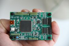
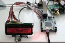
Sneak preview
Does this support I/O I2C ?? And about external clock masters of 44.1/48kHz??
Hp
It has 2 isolated I2S ports (in & out) and 2 isolated I2C ports. 2 crystals (e.g. 49.152MHz & 45.1584MHz). Currently it has 49.152MHz and 98.304MHz crystals. Unfortunately as is very common these days the I2C isolator chips got backordered from Mouser.
- Home
- Design & Build
- Equipment & Tools
- ADCs and DACs for audio instrumentation applications