there is a 2 way version of the BNC connector whose TLA always escapes me, but I might suggest a perusal of the Lemo or Fischer catlogs if you want wonderful connectors. For the very best many like hypertac (if they are not paying for them).
Someone on the ASR forum believes that the SMA connector is more suitable for a balanced low-distortion inputs of ADC, notch etc. I want to ask you guys, is anybody saw such custom SMA? I even prepared a picture of that, don't worry it is photoshop 😉
No, and I don’t think they exist. BNC exists in a triax version, but I don’t think it would be great for a balanced connection. Lemo connectors are rather bulky and certainly expensive.
I’ve ended up using SMA connectors for internal signal wiring, two per balanced connection. If cables are short, they work well.
syn08, ESS claimes 200kHz flat noise-floor but actually, I see some bump over 100kHz or so.
A big bump to -150 dB ;-D
//
Hi IVX,
Don't get fancy with connectors. A BNC is good into the GHz, better yet, it is a standard, expected connector. Even the RCA connector is good into the UHF band, more than good enough.
Internally, SMA or SMB connectors are good. Maybe even overkill. As syn08 says, a pair will do for a balanced connection. But what is it that you are running for a signal? If it is audio, use an XLR connector. It is designed for that use for starters. If you must, go for a mini XLR, but that is not so standard and will force everyone to make non-standard connectors up. Avoid doing that if you can.
-Chris
A careful build BNC connector may have a decent insertion loss up to 1GHz, but suffers from an original mechanical design sin; it does not define well a reference plane. As such, you will never get twice the same S11 and S22 parameters out of a BNC connection. Even the (otherwise not that great) F connectors are better in this respect.
Because you mentioned “because BNC is good into the GHz”. In fact it is not, the reflections will always be bad/inconsistent.
Otherwise, the inventor/designer of the RCA connector should be tarred and feathered in public. What kind of idiot designs a connector that connects first the hot wire and then the ground?
Otherwise, the inventor/designer of the RCA connector should be tarred and feathered in public. What kind of idiot designs a connector that connects first the hot wire and then the ground?
Completely agree when it comes to the RCA. But once mated it isn't a bad connection to a few hundred MHz. No, it would never be acceptable in the test and measurement field.
BNC connectors work okay. SMA are better for test and measurement for getting repeatable results. Of course, "N" connectors could also be used. I am looking at this question in context to what is being done. Looking at it from the standpoint of maximum performance I think distracts from the question. Besides, somehow I can't see the average person torquing the connectors to the proper torque every time they connect. Can you?
But I think we are talking about a balanced audio input that tops out much lower than 1 MHz. For that, the XLR connector was designed. I'm sure there are connectors designed for 50 GHz or so that we could argue would be better. Better at our frequencies? I doubt it. A single connector for both phases is indicated. A triax connector is just silly and expensive (plus really designed for signal and guard plus common).
You know I am not disagreeing with you syn08. I just think that we need to consider the application and people involved.
-Chris
Otherwise, the inventor/designer of the RCA connector should be tarred and feathered in public. What kind of idiot designs a connector that connects first the hot wire and then the ground?
+1.
TCD
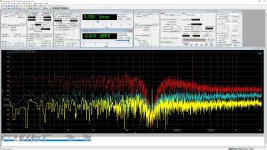
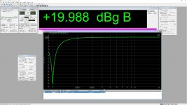
Guys, I wanna bragging again! The new iteration of Cosmos DAC with 1k_LPF option is On(i.e. DAC's output filtered) with Cosmos APU(notch filter 1/10k -30db ratio[-100db Ach means -130db THD+N], and LNA) shows residual THD+N -130db level! The previous version had -128db. 2nd and 3rd harmonics at -143db, 5th -157db, others at the noise-floor -170db. AP SYS2*** reads that like -120.5db THD+N and this is the noise level of that analyzer.
Attachments
What is this "Cosmos APU" notch and LNA? I suppose it's an analog notch filter, but I don't understand how you are specifying it.
And I would think you are showing the results for a balanced output, how are you balancing two notch filters to the required accuracy to suppress imbalance even distortions?
What are the color traces in the plot?
And I would think you are showing the results for a balanced output, how are you balancing two notch filters to the required accuracy to suppress imbalance even distortions?
What are the color traces in the plot?
Correct, Cosmos Analog Processing Unit is a notch 1/10k -30db + LNA 40/60db gain(ssm2019). Kind of microscope for an ADC, actually, for anyone, including laptop/desktop built-in audio inputs. Of course, APU has balanced inputs but for economic reasons its outputs are unbalanced.
The first pic shows a mismatch of harmonics levels 7.7V sine after APU(Red) vs direct AP input forced 10V range(Yellow) and forced 20V range(Cyan).
---------2nd------3rd-----5th
AP10 -144.21 -143.37 -150.16
AP20 -140.27 -134.89 -148
APU -144.27 -137.7 -152.17
AP's analog analyzer reading THD+N -100db from the APU output with -30db notching, hence there is -130db.
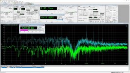
Another one pic shows APU output harmonics at 9.5V vs AP direct input forced to 20V range. AP's analog analyzer shows THD+N -120.5db of the sine which has at least -130db as APU can see.
The first pic shows a mismatch of harmonics levels 7.7V sine after APU(Red) vs direct AP input forced 10V range(Yellow) and forced 20V range(Cyan).
---------2nd------3rd-----5th
AP10 -144.21 -143.37 -150.16
AP20 -140.27 -134.89 -148
APU -144.27 -137.7 -152.17
AP's analog analyzer reading THD+N -100db from the APU output with -30db notching, hence there is -130db.
Another one pic shows APU output harmonics at 9.5V vs AP direct input forced to 20V range. AP's analog analyzer shows THD+N -120.5db of the sine which has at least -130db as APU can see.
You had considered the reality that any analog notch filter has a finite Q, aren’t you? As such, the 2nd, 3rd, etc... harmonics are attenuated as well, and this has to be accounted for. You can’t simply subtract from the AP measurement the notch attenuation, this would be a gross optimistic evaluation of the overall distortions.
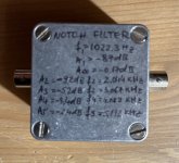
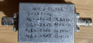
I've build my own twin T notch filters (attached), and after lots of component matching I was able to bring the notch down to -87dB while the H2 and H3 are close to the theoretical values for an ideal twin T, -9.2dB and -5.3dB, etc... But building another identical one (for a balanced notch filter) is almost impossible in practice, unless one would like to spend months in sorting components.
I was able to tune a second twin T notch filter for 8.86KHz down to -65.6dB, the H2, H3, ... attenuation are about the same as above, close to the theoretical values.
Attachments
Last edited:
well, 2kHz attenuated for .6db, should I really care? Just a little part of a positive feedback makes such "magic" 😀You had considered the reality that any analog notch filter has a finite Q, aren’t you? As such, the 2nd, 3rd, etc... harmonics are attenuated as well, and this has to be accounted for. You can’t simply subtract from the AP measurement the notch attenuation, this would be a gross optimistic evaluation of the overall distortions.
I've build my own twin T notch filter (attached), and after lots of component matching I was able to bring the notch down to -87dB while the H2 and H3 are close to the theoretical values for an ideal twin T, -9.2dB and -5.3dB, etc... But building another identical one (for a balanced notch filter) is almost impossible in practice, unless one would like to spend months in sorting components.
About can I simply subtract or not it can decide a simple experiment, if the THD+N formula is unknown. Look, I prepared some video again. AP has so-called D-gen(Sine(D/A)) i.e. DAC with so-so THD+N, exactly what we need for the experiment. I switching between AP D-gen direct measurement by the analog analyzer of AP and APU. The difference is exactly 30db. 😉
Why a notching ratio needs to simply substract from the THD+N reading?? - YouTube
Attachments
well, 2kHz attenuated for .6db, should I really care? Just a little part of a positive feedback makes such "magic" 😀
Well, I see you are not willing to disclose anything serious about the “magic” of this balanced analog notch filter with not more than 0.6dB attenuation of the H2. Apparently it is not a passive filter, so then there’s the legitimate question how do you build an active filter at these distortion levels., in particular if positive feedback is used.
But no need to get into such pesky details, go ahead and enjoy your bragging rights, I understand you have no good reason to educate your possible competitors (not me, of course, I couldn’t care less). It would be nice though if you would do this on your own thread(s).
Last edited:
Well, I see you are not willing to disclose anything serious about the “magic” of this balanced analog notch filter with not more than 0.6dB attenuation of the H2. Apparently it is not a passive filter, so then there’s the legitimate question how do you build an active filter at these distortion levels., in particular if positive feedback is used.
But no need to get into such pesky details, go ahead and enjoy your bragging rights, I understand you have no good reason to educate your possible competitors (not me, of course, I couldn’t care less). It would be nice though if you would do this on your own thread(s).
I was sure that everyone knows that trivial circuit. BTW, the second opamp isn't necessary, if the R/R impedance is low enough.
Attachments
Its not a problem to make high loop gain aplifier with ultra low distortion for active notch, but passive components in small size with needed linearity is a real problem.
I was sure that everyone knows that trivial circuit. BTW, the second opamp isn't necessary, if the R/R impedance is low enough.
So after lots of teeth extraction, we now know it’s an active filter with something like at least -140dB distortions, to allow clean measurements at -130dB. And how did you evaluate it’s distortion performances if your AP is limited at -120dB?
I not even going to mention the questionable noise performance of such an active filter, what is the Q? Or what R/C tolerances you used for a balanced filter to reject the common mode dirt? It’s still a mystery to me how you reached those numbers.
Last edited:
Nazar_lv, however, it's a solvable problem. I using Murata C0G highest voltage rating as I can find or place to my PCB, sometimes 2 caps in serial. Resistors are also should be as long as possible(MELF or TH) thin-film(Viking CSR0207) to avoid VCR affect the linearity in the required range. Actually, many opamps I've tried were fine in that filter but OPA1656 #1. Also, not so trivial task to make a buffer to such a low-impedance notch. I had the idea to use OPA1612 and maybe composite but I found an inexpensive Chinese opamp commonly used in China as an HPA(awful HPA with ugly clipping I have to say) with 100mA output and it works just fine there. No any secrets anymore 😉
- Home
- Design & Build
- Equipment & Tools
- ADCs and DACs for audio instrumentation applications