active rectifier will eliminate diode switching noise and result in cleaner supply lines. I know this can be snubbed out, but the snubbing may not be easy to get right for a diy'er
Your problem is assuming that im a pure subjectivist. Im not. Otherwise id be at audiokarma or some other audiophool forum being a fanatic. I do believe measurements matter and we should strive for their best but in the end it has to support the positive listening experience that is the final test of any audio. Audio that which is a human experience.I have seen enough crap on this forum, so yes, it does hosts bot high level electronics and myths ( IE crap ).
There is nothing wrong with the forum because of that, that's just how things are in real life.
Nothing ridiculous about what i said.
For years now, i design and built from scratch performance audio power amplifiers ( real measurable performance, not myths ), thus i do know what i am talking about.
Your problem is you just cannot acknowledge that audio is still only electronics, from the power supply to the driver coil.
What you perceive with your ears is subjective, not the amplifier it's self, and that is because of you, because of your knowledge, because of the invested money which MUST mean it's better ( one single example, tens of thousand of $ for a single signal cable, that's ridiculous but people still buy them ) , and mainly because of your own beliefs, none of them has anything to do with the performance of the amplifier it's self.
When music really sounds different it does so because some measurable difference in the audio system, either with the harmonics distribution, or the slew rate, or even the speaker cables them selves which if too thin they would have more DC resistance thus reducing the overall damping factor.
All of them are actual, measurable factors in the audio system, and all of them can influence the perceived sound.
The active rectifier on the other hand has no possible influence on any of them, it's job is solely to convert the alternating current in direct current, that's it, nothing else, the only variable is it's actual efficiency, and any eventual switching noise due to the mosfets switching between on and off, but that can be filtered or snubbed out, thus it cannot influence any of the amplifier's parameters.
And thats what i meant by build and listen, before you decided to without any reference take what i said out of my mouth and run with it. Smh...

That's a fabricated argument.You're advancing a solution made for industrial purposes while looking for a problem to solve in audio and the problem is not there...I think I saw so many posts about ringing caused by diode rectifiers that it almost appeared to be a true problem...except it isn't...
If you can't hear the active rectifier switching noise, I can't hear that damn ringing...let's just call it quits!
If you can't hear the active rectifier switching noise, I can't hear that damn ringing...let's just call it quits!
Last edited:
An active rectifier makes the instant of commutation worse wrt di/dt. The counter case is a valve diode with a relatively soft turn on and off.active rectifier will eliminate diode switching noise and result in cleaner supply lines. I know this can be snubbed out, but the snubbing may not be easy to get right for a diy'er
An active rectifier makes the instant of commutation worse wrt di/dt
di/dt (rate of change of current/time) ?
AFAIK, soft turn on and off is a good thing with regards to noise ?
An other bonus is less voltage drop and less generated heat with an active rectifier for class A amps ?
If I'm wrong with my assumptions, please correct me. 🙂
That was the reason for my post. When the diode current waveform falls rapidly from a high peak, it 'hits' zero and it is at that instant the di/dt is much higher for an ss diode than a valve diode, and the active diode would be the worst case.
I would appreciate if you could explain this in more detail.
Everything in audio electronics seems to have a but !!!
I would be happy to change my approach for a good explanation.
And then there is the multitude of diode choices .
Everything in audio electronics seems to have a but !!!
I would be happy to change my approach for a good explanation.
And then there is the multitude of diode choices .
Are you aware of the typical diode current waveform for a capacitor input filter, and how that waveform gets peakier and narrower as capacitance gets larger?
.....it 'hits' zero and it is at that instant the di/dt is much higher for an ss diode.....
yes, more capacitance, higher ripple within the same timeframe.
But I was not aware of shutoff issues with active rectifiers.
What kind of artifacts does this create ?
Also, may I ask what ss diode is your preferred one for rectifier.
The 'noise' typically happens when the diode current hits zero (turns off). An active diode has lower on-voltage and likely turns off faster, which would cause a worse disturbance to the secondary winding current. But maybe you are using an active diode that has a specially controlled turn on and off that is specifically designed to alleviate such a disturbance?
Reverse spike is nearly not observable with active rectification. Otoh, the active device is controlled by a PWM signal, so turns fully on and off at up to a few hundred kHz. The class D of rectification 🙂
Not sure why any of this matters one way, or the other. The fans clearly enjoy the sound better than any other rectifier. The armchair trolls don't care about sound anyway.
From where i am standing the only preference that matters is subjective. Among people i know about 3/4 love the sound, the rest stick to their old fave diodes.
If one wants to create a perfect rectifier, repurposed, off the shelf automotive and smps parts won't do. A purposefully designed circuit based on a zero crossing detector, comparators and non-pcm controlled fets is probably the way to go. Efficiency won't be high, unlike cost and complexity. Otoh, it will work at all voltage levels and be usable even with high voltage tubes. Will it beat mercury though?
Your 1170 controlled half wave rectifier is high voltage for tube gear?
Possibly PWM because of the high voltage?
The one I use is LT4320 with 3.6mΩ RDS(on) MosFets

According to tvicol, who has investigated this a lot, there is no need for snubbers in this circuit.
AFAIK, the snubbing is there to prevent ringing between the trafos secondary winding and the rectifier.
So perhaps this is not an issue with this kind of active rectifier ?
Possibly PWM because of the high voltage?
The one I use is LT4320 with 3.6mΩ RDS(on) MosFets
According to tvicol, who has investigated this a lot, there is no need for snubbers in this circuit.
AFAIK, the snubbing is there to prevent ringing between the trafos secondary winding and the rectifier.
So perhaps this is not an issue with this kind of active rectifier ?
If you want to get rid of diode switching noise, than Saligny can help you.
Not really. An amplifier with a lower voltage 25V would benefit.One more myth put down:
You got answer at #19.How and how much?
I have impression (based on many other threads) that you are seeking opportunity to argue over anything. 😆
The one I use is LT4320 with 3.6mΩ RDS(on) MosFets
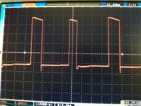
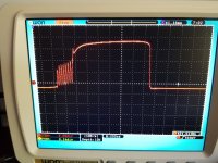
The 4320 is a different animal with its own little idiosyncrasies. As it provides no option to control the minimum on time it suffers false triggering. Especially bad at low load currents, below a 100mA. This is what the drive voltage at the gate of the topside transistor looks like. No idea how these pulses compare to the reverse recovery spike of normal diodes, but being close to 2.5v they are sufficient to turn the transistor on and off. Perhaps this will differ with various mosfet types. Tibi, who has done a lot of research could probably throw some light.
30mA, 100mA, 250mA
Attachments


Not completely correct. Have a look at the Quasimodo design note for a full explanation.AFAIK, the snubbing is there to prevent ringing between the trafos secondary winding and the rectifier.
The rectifier is only the "hammer" which stimulates the "bell" to ring. The problem (and the simple solution) is found in the bell.
I didn't used these rectifiers in audio, but I'm well aware of the phase delay problems when triggering thyristors and triacs on reactive loads like motors.The 4320 is a different animal with its own little idiosyncrasies. 9As it provides no option to control the minimum on time it suffers false triggering. Especially bad at low load currents, below a 100mA. This is what the drive voltage at the gate of the topside transistor looks like. No idea how these pulses compare to the reverse recovery spike of normal diodes, but being close to 2.5v they are sufficient to turn the transistor on and off. Perhaps this will differ with various mosfet types. Tibi, who has done a lot of research could probably throw some light.
30mA, 100mA, 250mA
I used to make zcd angle firing(moc chips ..thyristor, triacs) and vfd circuits for 1...5kwatts motors and test zcd circuits monitored by msp430 heaters and I also used to test hundreds of them per day in a fully controlled Labview environment. I don't really need to be lectured on these things, but I honestly think they are more usefull in llc-pfc power supplies than in audio.
As for lower than 25v supply efficiency...we have schotky diodes I think...or maybe better to let others express their measured concerns I never heard...
https://www.diyaudio.com/community/threads/why-schottktys.304746/post-5009456
It's the last time I repeat this: if you can't hear switching noises I can't hear diode ringing...
The rectifier is only the "hammer" which stimulates the "bell" to ring.
So the trafo secondary is the bell, the rectifier is the hammer, and the C//CR snubber is the rope you tie across the bell to stop it ringing?
A very nice and helpful article from Mark on diodes for linear power supplies in Linear Audio here.
From the article;
"When a diode stops conducting, the current doesn’t immediately return to zero but actually reverses to some value, THEN re-
turns to zero."
It seems like the diodes are more or less ranked by their recovery time. Lower recovery time, higher ranking, less ringing.
Here, PRR says the same thing.
standard silicon power rectifier ...would have a much "softer" reverse recovery because the turn-off event takes place much more slowly.
No. It "stays on" when it should be OFF. It pulls the power rail the wrong way. This leads to large current spikes, small dips in main cap voltage, and big kick-back in power transformer winding.
Is it possible that a rectifier based on the LT4320 stops very clean without entering the reverse area and therefore does not need snubbing?
30mA, 100mA, 250mA
I think most people here use LT4320 based rectifiers at over 1A. Perhaps yours would start cleanly at 1A?
What is the total gate charge, Qg of your MosFets?
This seems to be an important part of the MosFet spec to get them working properly.
Tibi suggests it should be lower than 50nC.
You seem to have looked into this a fair bit, so I'm just curious.
- Home
- Amplifiers
- Power Supplies
- Active rectifier or full bridge?