I know. And the ones i use are a bit higher at 76nC. Only i cannot see how this affects the false triggerings from the comparator once conduction starts. To me this seems like a design issue but of course i may be wrong.Tibi suggests it should be lower than 50nC.
For many audio applications, the di/dt of diode current as it hits zero is just too slow to induce ss diode reverse recovery. Note that examples of reverse recovery are often due to a contrived measurement setup. Similarly, aspects such as fet Qc etc are of negligible influence. Unless you are designing switchmode supplies, or have quite high dc current requirements, then imho you are chasing ghosts.
I have detected only negligible difference between 1N4007 and UF4007 in an example power supply, and that required a careful setup with good soundcard and quite low noise floor, and related to the DC supply, not any audio signal.
I have detected only negligible difference between 1N4007 and UF4007 in an example power supply, and that required a careful setup with good soundcard and quite low noise floor, and related to the DC supply, not any audio signal.
Is false triggering the reason why the datasheet states it needs a minimum amount of capacitance at the output, bad layout, non-suitable fets used or something else?I know. And the ones i use are a bit higher at 76nC. Only i cannot see how this affects the false triggerings from the comparator once conduction starts. To me this seems like a design issue but of course i may be wrong.
Could me one of those things, many or other.
It's all in the air what could be the cause.
The mechanism of false triggering seems simple.
A comparator compares output voltage to input and only turns on the mosfet when the input voltage exceeds the output. One can think of the comparator monitoring both sides of the body diode. No idea how sensitive the comparator is, or how big the hysteresis, but i assume these are optimised for best efficiency. The problem occurs once the voltage drop across the body diode exceeds the comparator threshold and the mosfet gets turned on. Suddenly the voltage drop across the body diode drops from whatever it has been down to 10mV or so. The comparator triggers again, this time turning the mosfet off.
The 1170 is capable of much higher frequencies and has more adjustments to combat false triggering. Per example it has a selectable dead time during which the mosfet cannot be turned off no matter how much the comparator wants it. Unfortunately this is not very useful for 50/60Hz as the scope of adjustment is geared towards much higher frequencies. The 1170 has also a user adjustable filter on the comparator sense pin in order to avoid switching noise at the output to cause false triggering.
This seems to be an issue with all commercial sync rectifiers. I guess a couple of spikes per period are no biggie in a car, as long as efficiency stays high.
Please note, all the above is speculation based on my experiments and reading the datasheets. It is not the gospel truth, I may be wrong.
It seems we have come to believe that diode sound is explained with the reverse recovery spike and the consequent resonance. This is also a speculation.
Is false triggering the reason why the datasheet states it needs a minimum amount of capacitance at the output, bad layout, non-suitable fets used or something else?
A minimum amount of capacitance is probably essential for the ic to work. The very first half period is rectified by the body diode, so that the output capacitor can store enough energy to power the comparator and gate drive during the next period. The decoupling capacitor has probably more to do with false triggering as it filters out spikes close to the comparator.
Sounds right for the decoupling cap. I am still puzzled by the triggering though, especially since the LT is only designed to rectify AC mains basically, iow very low frequencies. Being current dependent, it would be nice to see the relation of the Drain to Source voltage at the same time scale (channel B of the scope I guess).A minimum amount of capacitance is probably essential for the ic to work. The very first half period is rectified by the body diode, so that the output capacitor can store enough energy to power the comparator and gate drive during the next period. The decoupling capacitor has probably more to do with false triggering as it filters out spikes close to the comparator.
it would be nice to see the relation of the Drain to Source voltage
First pic shows the big picture, red is gate voltage, yellow - DS. Second shows the switch on zoomed and last, the switch off zoomed. Please note the different voltage scales. The 1170S comparator hysteresis is 90mV and we can probably assume the 4320 is similar. Load current is only 30mA, things improve at higher currents.
Attachments
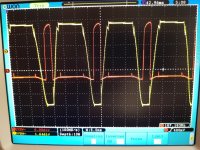
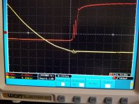
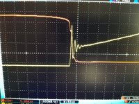

Great, thanks for taking the time analog_sa, I will see when I have time to also take some scope shots of my own. Need time as well as location effort to pull that off, so bear with me.First pic shows the big picture, red is gate voltage, yellow - DS. Second shows the switch on zoomed and last, the switch off zoomed. Please note the different voltage scales. The 1170S comparator hysteresis is 90mV and we can probably assume the 4320 is similar. Load current is only 30mA, things improve at higher currents.
There doesn't seem to be a problem at high currents. Can you test this at a 100mA? A lot of class AB amps draw a similar current at low volume.
I designed a LLC-converter delivering about 40V/10A DC. The synchronous rectifier with all its complexity saves a lot of board space by reducing the rectifier heat sink considerably. Another bonus is the lack of output voltage overshoot at low load observed with diode rectification making an unregulated, fixed frequency LLC applicable.
I replaced quite a few Jadis amps (heaters) with the 4320, also some DAC circuits. The Jadis' factory diode bridges (2 in parallel) break down after about 8 years. Only because the screws that fit them tight to the chassis get loose and they overheat). Depending on the capacitance behind them you can run many amps without cooling them (TO-220's).I designed a LLC-converter delivering about 40V/10A DC. The synchronous rectifier with all its complexity saves a lot of board space by reducing the rectifier heat sink considerably. Another bonus is the lack of output voltage overshoot at low load observed with diode rectification making an unregulated, fixed frequency LLC applicable.
Btw, what do you mean exactly by output overshoot?
Load 20 mA. Still perfectly clean triggering. Now, what is different with your rectifier. Do you have CLC after the active bridge?
If you zoom the trailing edge a bit more you'll see ringing. It's hinted clearly even at this level of zoom.
The rectifier i am examining is not part of an amp, it is just on my bench. 10mF connected with 10cm long wires and resistive loads. I have several working amps which use the same boards, one draws about 2.5A per channel at idle, the others are AB @ about 300mA. Will try to test in situ tomorrow.
With no load the LLC-converter produces leading voltage spikes on the secondary. These contain little energy, so it takes some time to load the bulk capacitor to overvoltage. Keep in mind the diode only conducts in forward direction, so this works like a peak-hold circuitry. On the other hand, the sync rect - while enabled - conducts in both directions. So this overvoltage cannot build up as the bulk cap will be permanently discharged to the secondary plateau-voltage following the leading spike.Btw, what do you mean exactly by output overshoot?
You made an LLC-converter at 100Hz?With no load the LLC-converter produces leading voltage spikes on the secondary. These contain little energy, so it takes some time to load the bulk capacitor to overvoltage. Keep in mind the diode only conducts in forward direction, so this works like a peak-hold circuitry. On the other hand, the sync rect - while enabled - conducts in both directions. So this overvoltage cannot build up as the bulk cap will be permanently discharged to the secondary plateau-voltage following the leading spike.
No, closer to 100kHz. This is an application where this makes sense.You made an LLC-converter at 100Hz?
That'swhat I thought. So where do you use the 4320, which is designed for 120 Hz max?No, closer to 100kHz. This is an application where this makes sense.
From your description you seem to place it secondary in the LLC, what else replaces a single diode?
I never used that chip. Yes, it is secondary side, center-tapped winding and two NMOS-switches driven by some controller-chip.That'swhat I thought. So where do you use the 4320, which is designed for 120 Hz max?
From your description you seem to place it secondary in the LLC, what else replaces a single diode?
- Home
- Amplifiers
- Power Supplies
- Active rectifier or full bridge?