Maybe so, but the response looks basically flat until ~700 Hz, with the -3 dB point arguably just above 600 Hz. I figure you'd have better HD3 if the response was -6 dB at 800 Hz?LR4 electrically or acoustically? BW2 electrically already gives a slope around 6th order. Not sure why the raw system is 4th order acoustically.
create an LR4 slope with rephase, import it to REW and choose an electronic filter that creates a measured acoustic slope matching your LR4 from rephase. when imported to REW, the rephase filter sits at 0 dB at the bottom of your scale / window. change trace and add the required dB to pull it up to the level of your measurement.
Crap, sorry, I somehow thought you were doing a HP at 800 Hz, not 600 Hz. Carry on.Maybe so, but the response looks basically flat until ~700 Hz, with the -3 dB point arguably just above 600 Hz. I figure you'd have better HD3 if the response was -6 dB at 800 Hz?

Just sharing because it looked cool to me. All sliced up and ready to send to the printer. I really appreciate the designs being made to not require supports. guessing around a week if all goes well. Wish me, and my dumb printer luck.

@Olombo I'm a bit late to the party here, but which line on the graph represents each of your measurements? I see four lines, but three things you're measuring - what does the red line represent?
Measured today on 460 horn:
- modified DCX464
- unmodified DCX464 with original 1.4 adapter
- BMS 4554 "long adapter"
Results:
- The insert kills the LF gain. I assume it cannot "breathe" enough through the smaller channel. Unfortunately I have no idea how I could change this without affecting the HF part. Red trace is unmodified DCX the others the angle measurements of the modified DCX....
- BMS performs as promised. Great work Marcel!

A bit disappointed this evening as I had quite some hope for the DCX mod. Well...maybe I get another idea how to improve. Suggestings welcome 🙂
@mabat Do you know what the implications of scaling the A520G2 horn up might be? Let's say from 520mm to 620mm? Let's say the curve profile stays identical, and the throat exit and everything else remain the same curve? I tried simulating in AKABAK but - to be honest - I'm coming at this from a designer's perspective, so I'm really struggling with the program. The reason I ask is I'm designing a set of speakers that are starting from an aesthetic and overall idea (2 way with large horn on top), and trying to tweak existing designs to match the proportions and scale I'm looking for. I'm thinking about marrying the SB Audience Rosso CDN-T with one of your horns on top of a Faital Pro 15FR400 foor the bass section, and I'd like to potentially scale up the horn section to 24" / 620mm+/-, simply for aesthetic reasons, as it sits better on top of the cabinet below. I've kind of got a "tapered" cabinet going on, so to get the woofer within a reasonable driver spacing range of the horn means that if I scale the whole thing down, I'd likely have to go to a 12" instead of a 15" woofer - probably not the end of the world but given the love for the aforementioned woofer in these types of setups I'm hesitant to go elsewhere.
I originally was going to go with the B&C DCX464 to cover a larger spectrum, but I haven't yet seen it implemented in one of your horns yet and I'm a bit hesitant to try it with my own design and curvature, even if it is based on existing designs.
I'm also going to be fabricating the horn out of wood, with a few modifications that are likely to affect the Frequency Response to some small degree, which I think I can live with as a tradeoff to the aesthetic I'm looking for.
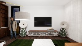
Attached is a rendering of the "mockup" of the early speaker design in my living space. Speakers will be active and biamped with a 2A3 for the horn and a 275w Class AB for the woofer.
I originally was going to go with the B&C DCX464 to cover a larger spectrum, but I haven't yet seen it implemented in one of your horns yet and I'm a bit hesitant to try it with my own design and curvature, even if it is based on existing designs.
I'm also going to be fabricating the horn out of wood, with a few modifications that are likely to affect the Frequency Response to some small degree, which I think I can live with as a tradeoff to the aesthetic I'm looking for.
Attached is a rendering of the "mockup" of the early speaker design in my living space. Speakers will be active and biamped with a 2A3 for the horn and a 275w Class AB for the woofer.
Attachments
You can make your own "A620G2", retaining the possibility to still use all the Gen2 adapters, simply by modifying A460G2:

Code:
; ATH A620G2 / based on A460G2
R-OSSE = {
  R = 310
  r0 = 17.824
  a0 = 4.359
; everything else stays the same
}Or if you already have the A520G2, you can modify that one:

Code:
; ATH A620G2 / based on A520G2
R-OSSE = {
  R = 310
  r0 = 17.916
  a0 = 4.139
; everything else stays the same
}And Maybe i will! Haha I have an elegoo neptune max so I can print over 30 inch horn. Sb audience Rosso 65 would pair nicely, maybe celestion?... what are the loading capabilities? Is it 4x the width of the mouth?You can make your own "A620G2"
One thing I think about with single multi-octave horns vs multiple horns is this:
Is point source "better" than hornloading every 2 octaves to reduce distortion and increase spl? Obviously one is cheaper and easier... I suppose this is a subjective choice and can only be understood first hand. Anyone with first hand opinions on imaging, soundstage scale etc?
Is point source "better" than hornloading every 2 octaves to reduce distortion and increase spl? Obviously one is cheaper and easier... I suppose this is a subjective choice and can only be understood first hand. Anyone with first hand opinions on imaging, soundstage scale etc?
@mabat thanks for simulating that - it is kind of interesting that the differences between the A460, 520 and 620 are probably so minor as to be academic.
I will be honest - I am doing all of this study from a work-supplied computer, which is why I rebuilt the R-OSSE formula into a parametric grasshopper script because they have restrictions on the type of software we can install, which unfortunately includes your horn generator. I can plug all of those numbers into the script, but I don't have a reference for the rest of the variables in the formula.
I did purchase the A520G2 file simply to get the geometry and curvature for my own reference, and I can get pretty close to approximating it with the Grasshopper but dialing it in perfectly to match the A520 is tough given the number of variables.
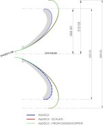
It seems to me at least logically if one were to simply uniformly scale the curve at the point of exit from the adapter, it should more or less get me what I'm after and should maintain the performance of the 520.
I have an image showing how I'm doing it geometrically. Does this make sense at least logically?
; ATH A620G2 / based on A520G2 R-OSSE = { R = 310 r0 = 17.916 a0 = 4.139 ; everything else stays the same }
I will be honest - I am doing all of this study from a work-supplied computer, which is why I rebuilt the R-OSSE formula into a parametric grasshopper script because they have restrictions on the type of software we can install, which unfortunately includes your horn generator. I can plug all of those numbers into the script, but I don't have a reference for the rest of the variables in the formula.
I did purchase the A520G2 file simply to get the geometry and curvature for my own reference, and I can get pretty close to approximating it with the Grasshopper but dialing it in perfectly to match the A520 is tough given the number of variables.
It seems to me at least logically if one were to simply uniformly scale the curve at the point of exit from the adapter, it should more or less get me what I'm after and should maintain the performance of the 520.
I have an image showing how I'm doing it geometrically. Does this make sense at least logically?
Attachments

@mabat apologies, I finally found the input variables in the associated text file with the A520 -
turns out my intuitions were pretty correct - here's the same graph as above but with the Grasshopper-derived script with the adjustments to the variables you suggested. The scaled curved and the formula-derived curve are almost identical - with a deviation of maybe 1mm in the most extreme case.
turns out my intuitions were pretty correct - here's the same graph as above but with the Grasshopper-derived script with the adjustments to the variables you suggested. The scaled curved and the formula-derived curve are almost identical - with a deviation of maybe 1mm in the most extreme case.
Attachments
in keeping with making hifi horns more accessible, I just wanted to share findings with a520g2 horns and $45 nsd2005 drivers I bought. These are measured differences between the stock rear chamber and a prototype metamaterial rear chamber. My point here is not to show a perfect response but if they've been improved or not, and what budget drivers are capable of in Advanced-Transition Horns.
Thumbnail to the left is the factory rear chamber, to the right is the metamaterial.


Blue line is stock Red is Metamaterial 1/6 smoothing. Again, not the best but exceptional value imo.

Left is stock, right is metamaterial. I left the cursor at 903hz for both measurements. The measured output of the metamaterial was slightly higher overall. we're mainly looking at everything below 3k, above that i believe is largely unaffected by chamber resonance and simply diaphragm breakup. (which will be addressed when my aquaplas order arrives). overall, the distortion profile is smoother and the problem areas have gone down about nearly 10db. You might notice the 3rd harmonic has gone up about 3db in certain areas and this is likely because it's a prototype and the 2-piece design was not effectively secured.


the design process was simple. all i did was measure the driver for fitment and created a shape. i inserted the shape into orcaslicer and used the hilbert curve pattern at 30% infill. I gave no consideration to chamber volume or anything so there is definitely room for improvement. I believe metamaterial could improve the first 3 octaves of any driver in these horns for basically no money.
Thumbnail to the left is the factory rear chamber, to the right is the metamaterial.
Blue line is stock Red is Metamaterial 1/6 smoothing. Again, not the best but exceptional value imo.
Left is stock, right is metamaterial. I left the cursor at 903hz for both measurements. The measured output of the metamaterial was slightly higher overall. we're mainly looking at everything below 3k, above that i believe is largely unaffected by chamber resonance and simply diaphragm breakup. (which will be addressed when my aquaplas order arrives). overall, the distortion profile is smoother and the problem areas have gone down about nearly 10db. You might notice the 3rd harmonic has gone up about 3db in certain areas and this is likely because it's a prototype and the 2-piece design was not effectively secured.
the design process was simple. all i did was measure the driver for fitment and created a shape. i inserted the shape into orcaslicer and used the hilbert curve pattern at 30% infill. I gave no consideration to chamber volume or anything so there is definitely room for improvement. I believe metamaterial could improve the first 3 octaves of any driver in these horns for basically no money.
If I want to make a A460 with the BMS adapter and a broader dispersion angle (surrounds in the home cinema) I have to adjust the opening angle in the provided script. So far so easy. But I assume I need to keep the throat impedance in a similar region as the original to keep the low frequency loading of the BMS. I have many parameters to play with....but any reconmendation which ones may lead to a quick success?
Loading is set by the wall angle. If the angle is increased for a wider coverage, the loading is decreased, i.e. the "cutoff" (no matter how it's defined) moves higher in frequency. It's not really possible to make it wider-radiating and retain the same loading (see below). All you can hope for is an additional resonance, but for larger angles this gets ugly pretty quickly.
A460D + BMS 4554 (https://www.at-horns.eu/A460D.html):

Basic distortion sweeps (2nd, 3rd, 4th):


A460D + BMS 4554 (https://www.at-horns.eu/A460D.html):
Basic distortion sweeps (2nd, 3rd, 4th):
Last edited:
Hi,
thanks Marcel. This indication saves a lot of time. I might switch to e.g. Rosso 65 for the surrounds then. I assume they suffer less from less loading and might still provide acceptable XO frequency.
thanks Marcel. This indication saves a lot of time. I might switch to e.g. Rosso 65 for the surrounds then. I assume they suffer less from less loading and might still provide acceptable XO frequency.
Not even if the extension adapter is a relatively long tube, only after which the wide dispersion starts with the waveguide?
Hi!
I´m playing around trying to create a waveguide for line sources. Source is rectangular, but height is much greater than width.
Works well with the OSSE parameters for horizontal and vertical curvature.
Is there in ATH the posibility for doing this with R-OSSE profiles for horizontal coverage, combined with plain (0°) base and lid?
Marcel, in Post 11,545 you mentioned the "D=" for diagonal curvature when it comes to rectangular sources, but that´s not useful, when hight is much greater than width of the source.
Thank you!
- Home
- Loudspeakers
- Multi-Way
- Acoustic Horn Design – The Easy Way (Ath4)