yes and colors are responsing with Chet photograph ones. That is nice looking and interior (not that easy with diy !) 👍
I too prefer that pasta orange strainer look than the threatening black crow saw looking (
)
I too prefer that pasta orange strainer look than the threatening black crow saw looking (
Thank you for your kind words 🙂 . The woofers are hidden behind the horns (coaxial design).Dmitrij_S - I'm really fascinated by the appearance, it's just marvelous. It's so unusual yet so easy on the eye. Bravo. I contemplated making something similar but would've never thought it can look so great in the end.
- So, where are the woofers? 🙂
A little about the project. The box acoustic design is Double Chamber Reflex, the ports outputs are place on the back wall. The box proportions are mathematically optimized. It took me almost three months to study the scientific literature on architectural acoustics and write my own code to perform standing waves optimization (I used the modal decomposition method which allows to solve the wave equation analytically for a rectangular box). Unexpectedly for myself, it turned out that the proportions of the box that are optimal from an acoustic point of view are also very pleasing to the eye (of course, design is a matter of taste). I also spent some time on modeling parasitic radiation from the walls of the box, organ pipe resonances of ports and other trifles.
The loudspeakers are controlled by the DSP. Since up to that time I had not had to deal with DSP at all, a decent part of the time I had to spend on learning the basics of DSP and developing of digital filters. As a result, hybrid IIR and FIR filter was designed.
Most of the time, about half a year, was spent on modeling and prototyping the horn. Coaxial construction significantly complicated design since a horn determines acoustical interaction between HF and LF drivers.
In total, it took almost a year to develop the project, most of which was spent on mathematical modeling (professional deformation affects 🙂 ). and the resulting aesthetic design is a "by-product of mathematics".
A little about design. The design has gradually evolved during all stages of the project development. The only thing I was clearly aware of was that I didn't understand aesthetic design at all 🙂. Therefore, the credo that I chose was "the less aesthetic details, the less chance to fail design!". I figured that it would be best to go for a minimalist design with some slight accents. In my case, the horn itself became the very accent. Perhaps a competent designer would add some more accents and make the project even more attractive.
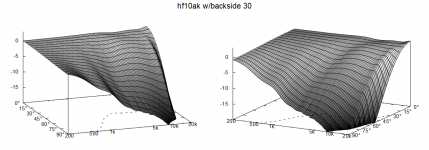
Alright played with the backside some.
If someone wants to make such waveguide that has enclosing backside to eliminate diffraction altogether, then I suggest to optimize the R-OSSE definition by using tmax > 1 first. Then, if the backside did not end up practical to build use the new bezier backside definition or Profile coordinates file to shape the backside further to make it more practical.
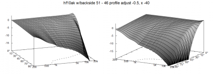
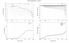
Here is profile I came up with for my project, backside is done by tmax so no tricks. Graphs show no diffraction, about target DI.
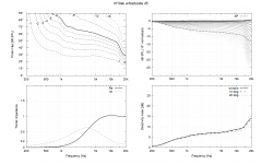
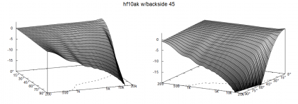
Not sure if its coincidence or not but a bezier curve seems to match almost perfectly tmax backside with the R-OSSE definition here. I used Desmos as reference to match the bezier to R-OSSE tmax and then script to make these sims. Custom script is output here and seems to be working as results match above.
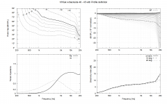
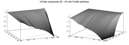
Following are some manipulations of the backside, making it longer and rounder and so on compared to backside made with just tmax. As you see the waves on the fall plot are due to sound going all the way around the waveguide and can be minimized by manipulating shape of the backside. I think these are getting almost as good as it gets because we cannot stop sound propagating around freestanding object so some of the wavyness will stay no matter what
Rounder back, same depth, kind of apple shape
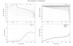
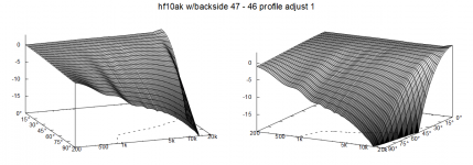
Rounder and elongated back
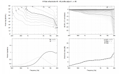
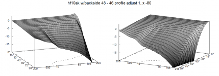
This is just elongated back

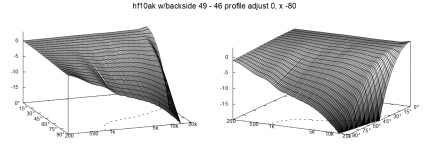
Little bit less elongation
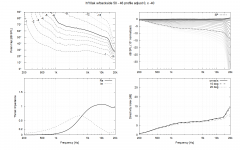
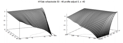
More pointy back
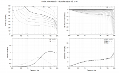
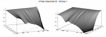
edit. for completeness sake here the same R-OSSE profile without backside, tmax=1 so edge diffraction effects are visible.
If someone wants to make such waveguide that has enclosing backside to eliminate diffraction altogether, then I suggest to optimize the R-OSSE definition by using tmax > 1 first. Then, if the backside did not end up practical to build use the new bezier backside definition or Profile coordinates file to shape the backside further to make it more practical.
Here is profile I came up with for my project, backside is done by tmax so no tricks. Graphs show no diffraction, about target DI.


Not sure if its coincidence or not but a bezier curve seems to match almost perfectly tmax backside with the R-OSSE definition here. I used Desmos as reference to match the bezier to R-OSSE tmax and then script to make these sims. Custom script is output here and seems to be working as results match above.


Following are some manipulations of the backside, making it longer and rounder and so on compared to backside made with just tmax. As you see the waves on the fall plot are due to sound going all the way around the waveguide and can be minimized by manipulating shape of the backside. I think these are getting almost as good as it gets because we cannot stop sound propagating around freestanding object so some of the wavyness will stay no matter what
Rounder back, same depth, kind of apple shape


Rounder and elongated back


This is just elongated back


Little bit less elongation


More pointy back


edit. for completeness sake here the same R-OSSE profile without backside, tmax=1 so edge diffraction effects are visible.


Last edited:
That's what I expected but then they are very well hidden indeed 🙂The woofers are hidden behind the horns (coaxial design).
Thanks! There is lots of questions still, like how to actually manufacture them so that the driver can be inserted inside and so on 🙂 Also, there is still some 0.25db kink in DI around 5kHz to optimize in R-OSSE definition. I have no automation script so its not perfect, just imagination and hand crank so it was some work.
Here is the R-OSSE definition in desmos https://www.desmos.com/calculator/kzpt3tyi9f also showing my simple bezier backside matching R-OSSE curve. These parameters (R-OSSE alone with tmax > 1) ought to yield results above labeled number 45.
Here is the R-OSSE definition in desmos https://www.desmos.com/calculator/kzpt3tyi9f also showing my simple bezier backside matching R-OSSE curve. These parameters (R-OSSE alone with tmax > 1) ought to yield results above labeled number 45.
Last edited:
Split it into two parts, I guess. Obviously, the prolonged back side works well for a low DI design - there's no drawback then (other than having a low DI design 🙂).
Yeah split probably at t = 1
I think the waveguide can be made for somewhat higher DI as well, I've got some pretty nice versions with bit higher DI and bit lower, with same radius. Try your optimizer script for DI of your liking and tmax something sensible. But its true the overall DI is bit lower and tend to beaming compared to same size tmax=1 waveguide without backside. I have only explored what I need so not sure how it works out for higher DI, looks promising though.
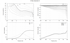
edit. This example hints DI closer to 10db can be reached around 2-3kHz and probably held quite constant there. This is too high DI for my project so didn't check it out further. This is some R-OSSE definition with tmax > 1.
--
I've got an idea which might reduce sound around the device even more. Pointy back on above examples seem to have least ripple due to sound all the way aorund the device and I think its partly due to backside randomizing the path lengths enough and partly due to diffraction at the pointy end making similar effect as with tmax=1 waveguides, but now towards off-axis. Basically, sound diffracting bad on the pointy back splits roughly in half (the backwave moving toward listener and the part that went around and also moving toward listener) and the same happens for both sides simultaneously resulting cancellation on each side. Black hole of sorts 🙂
What I think would maximize the pointy back effect would be to morph the pointy back to a cross. Bezier end point y -coordinate could be modified with the superformula, need to try some day 🙂 Example https://www.desmos.com/calculator/idyzjboxk6
I think the waveguide can be made for somewhat higher DI as well, I've got some pretty nice versions with bit higher DI and bit lower, with same radius. Try your optimizer script for DI of your liking and tmax something sensible. But its true the overall DI is bit lower and tend to beaming compared to same size tmax=1 waveguide without backside. I have only explored what I need so not sure how it works out for higher DI, looks promising though.
edit. This example hints DI closer to 10db can be reached around 2-3kHz and probably held quite constant there. This is too high DI for my project so didn't check it out further. This is some R-OSSE definition with tmax > 1.


--
I've got an idea which might reduce sound around the device even more. Pointy back on above examples seem to have least ripple due to sound all the way aorund the device and I think its partly due to backside randomizing the path lengths enough and partly due to diffraction at the pointy end making similar effect as with tmax=1 waveguides, but now towards off-axis. Basically, sound diffracting bad on the pointy back splits roughly in half (the backwave moving toward listener and the part that went around and also moving toward listener) and the same happens for both sides simultaneously resulting cancellation on each side. Black hole of sorts 🙂
What I think would maximize the pointy back effect would be to morph the pointy back to a cross. Bezier end point y -coordinate could be modified with the superformula, need to try some day 🙂 Example https://www.desmos.com/calculator/idyzjboxk6
Last edited:
@tmuikku: Dont know if this helps but I 3D printed the enclosure for my coaxial mid+tweeter in 3 parts. Each part had a threaded end to which the other part would fit to. Few pics


The gaps in the above enclosure go away if i rotate each part to cover the full length of the thread
The gaps in the above enclosure go away if i rotate each part to cover the full length of the thread
Cool, thanks! was it easy to print or did the threading need some special things to take account for it to work? In general, I'm not too familiar with 3D printing and could imagine small defect in the thread would prevent it from working. How tight tolerance there is and so on?
Last edited:
In general, 3D printing part was easy. In the above pic middle section of the enclosure had an issue with perfectly fitting the section with driver in the front. This was because I had printed with the threaded part of the middle section on thr plate where some supports were attached to (i didn't know how to selectively remove supports from unwanted areas at the time). There was some warping as well. So while i removed the supports, i accidentally tore off some of the threading as well.Cool, thanks! was it easy to print or did the threading need some special things to take account for it to work? In general, I'm not too familiar with 3D printing and could imagine small defect in the thread would prevent it from working. How tight tolerance there is and so on?
When i printed the last section at the back, This issue did not happen and it would fit perfectly.
Drinking coffee and spotted few observations from the set.
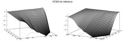
Here is standard ST260 for comparison with same sim and plot settings, pretty good 😀
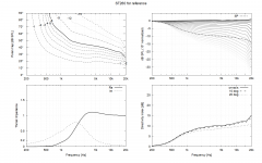
Following graphs are from the earlier post, my profile with and without backside. The one without backside is generated by ATH and the one with backside is done through Profile coordinates generated from R-OSSE formula and custom backside curve with my custom script.
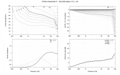
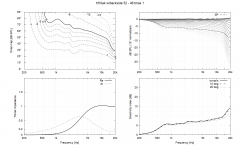
Comparing impedance graphs and top octave its clear there is some difference on resolution, amount of nodes in nodes.txt is same but I'm just cranking coordinates out with t/nodes steps, perhaps nodes should be closer together at throat area for better accuracy? Also radius seems to go all the way up to 136mm on my script while it should stop at 130mm so there must be some error somewhere. Well, they are pretty close, and its real simulation no matter what generated the curve so 😀 Still some work to do.
Another thing, comparing DI it seems edge diffraction on the device without backside extends DI roughly half an octave lower. Estimating by eye both ST260 and my profile without backside have roughly 6db DI around ~700Hz while the one without has it perhaps around ~1000Hz.
As mabat said such device is usable for lower DI systems without too much of a size penalty.
edit. increased radius from 130mm to 185mm, so bigger 50% in diameter, to reach DI of about 6db around 700Hz. Perhaps some optimization size could come down some. Definitely bigger device than ST260 for sure, good work diffraction, good work mabat 🙂
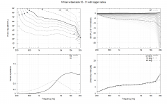
Here is standard ST260 for comparison with same sim and plot settings, pretty good 😀


Following graphs are from the earlier post, my profile with and without backside. The one without backside is generated by ATH and the one with backside is done through Profile coordinates generated from R-OSSE formula and custom backside curve with my custom script.


Comparing impedance graphs and top octave its clear there is some difference on resolution, amount of nodes in nodes.txt is same but I'm just cranking coordinates out with t/nodes steps, perhaps nodes should be closer together at throat area for better accuracy? Also radius seems to go all the way up to 136mm on my script while it should stop at 130mm so there must be some error somewhere. Well, they are pretty close, and its real simulation no matter what generated the curve so 😀 Still some work to do.
Another thing, comparing DI it seems edge diffraction on the device without backside extends DI roughly half an octave lower. Estimating by eye both ST260 and my profile without backside have roughly 6db DI around ~700Hz while the one without has it perhaps around ~1000Hz.
As mabat said such device is usable for lower DI systems without too much of a size penalty.
edit. increased radius from 130mm to 185mm, so bigger 50% in diameter, to reach DI of about 6db around 700Hz. Perhaps some optimization size could come down some. Definitely bigger device than ST260 for sure, good work diffraction, good work mabat 🙂

Last edited:
BTW, here's a convenient Desmos graph for all the parameters that can be entered directly into an Ath script:
https://www.desmos.com/calculator/n6i73rqgik
You can manually drag the three color dots with mouse to set the shape of the back curve.
xb, u1, u2, w1, w2 are directly the numbers for Mesh.RearCubic, in this order.

https://www.desmos.com/calculator/n6i73rqgik
You can manually drag the three color dots with mouse to set the shape of the back curve.
xb, u1, u2, w1, w2 are directly the numbers for Mesh.RearCubic, in this order.
Did you generate FRD for a full spin? What matters is how the DI integrates after the crossover, something to find out with VCad.Drinking coffee and spotted few observations from the set.
Here is standard ST260 for comparison with same sim and plot settings, pretty good 😀
View attachment 1129302View attachment 1129303
Hi, yeah its a quick process and posted one graph two weeks ago. Plan is to tailor fit waveguide to a system so it is mandatory sooner or later. I need still more simulation to see what can be done and if its worth it. I have ST260 prototypes now and might as well try another prototype before ordering quality finish.
I specifically meant the new minimum diffraction waveguide with rising DI at the bottom end of its passband. It could even be beneficial to have extra energy in the crossover zone in the form of the widening pattern of the tweeter. This is why I was asking if you had extracted FRDs yet.
Yeah I'm not zoomed in too closely yet, I would first look it makes continuous DI for the system, is this what you mean?
In my app crossover is around 1-2khz, which part of slope you mean? Rise of the DI is more gentle here with these sims and I'm gonna use it with cardioid mid box which has about 6db DI below xo, shooting up past beaming. Idea is to crossover below the mid woofer beaming, below its diffraction, and I've reasoned gentle slope on the waveguide would work but lets see.
Usually waveguide is crossed over to a woofer where the woofer narrows its response first with baffle diffraction and continuing up to beaming, DI gets quite high and slope is kind of rapid so perhaps ST260 works better as it also has help from diffraction making slope similar to woofer(box) as long as they are similar in size. If waveguide is non diffracting also woofer box should be, to match.
It is ongoing investigation, I'd be glad if you have insight to post on this.
Getting the crossover right is probably the hardest part of any design. Including a proper measurement (which is an absolute must if it's supposed to work well), it's really a hard work. But we do enjoy that, that's the point of doing it, isn't it 🙂
I don't see a reason why any of these devices shouldn't work (very) well, provided enough atttention is given to the crossover and the overall design of the system. But it's just an ingredient.
I don't see a reason why any of these devices shouldn't work (very) well, provided enough atttention is given to the crossover and the overall design of the system. But it's just an ingredient.
Last edited:
Or in other words get the physical construct so that measurements are so good the crossover is just a task and not a struggle, a good system design as you suggest. Listening to music all the time no matter what the system and if all the tinkering gets better sound then why not, its fun time nevertheless 🙂
Last edited:
- Home
- Loudspeakers
- Multi-Way
- Acoustic Horn Design – The Easy Way (Ath4)