If you look at Gamma tone filter responses (filters that represent our hearing) (the IRs) they show that this time gets shorter and shorter at HFs, but fairly constant at LFs. That's why we can detect early reflections at HFs in a small room, but not at LFs.From an ear-brain perspective, what should the integration time be for a frequency domain measurement that would be valid for FFT into an IR that mean something for a human? I'm sure its frequency dependant... wesayso uses 6 cycles for his EQ adventures...
//
Hello,
I have been reading this thread for a while. I actually read most of it and but that took a whole and so I already forgot most of it again.😛
But it was extremely informative. Thanks to you all and in particular to mabat, great work!
As the discussion has turned to crossovers I might add my 2ct.
I have been struggling with the acoustic side of combining two drivers. ST260 is a great WG and there is not much left to be done to have a superb tweeter. Just adapt to the exit angle and size of the preferred CD and there you go. But I wanted to have a bit lower DI to get a small increase in DI between cardioid LF and HF produced by WG. ST260 has DI≈12dB at 10kHz and I wanted to get to ≈10dB.
That took some work and after doing about 100 iterations by hand 🥴 I learned ATH a bit and arrived at the following parameter set.
WG_260_ND3N

This is not perfect in the top octave but 15 kHz is the limit for me anyway and I want to cross as low as possible, preferably 700 Hz or below.
The crossover would have to take care of the DI in the crossover region.
But how to combine this with a woofer?
There is a thread (here? I cannot find it anymore 🙁 ) about combining a WG with four woofers in a quasi-coaxial geometry. i liked the idea and so my idea is something like this with the woofers on the side for an active cardioid.
I do not think this will work well with a ST260-style WG with open back. A graph from Dmitrij_S in Post #2,558 gave me the idea to put the WG with a closed back (well rounded) in front of the woofers. Something like this.

So I edited the nodes.txt file for some time and finally got this design that would fit around the ND3N which you can see in the middle of back.


From tmuikku we know the effect of the backside for FR/DI and so there is little surprise.

It is smoother and DI below 1.2 kHz is a bit lower than before. I like the result. It is "shorter" than most of the designs of tmuikku.
But now what happens if one puts this in front of the woofer box? I am by far not good enough with ABEC to simulate this so I approximated it with ATH in axisymmetric mode (with a tiny rod that connects the 2 parts). ATH is really great!
But the result is not so great. Easy hunting for "diffraction".😀


This is the very same WG as before! Of course this is the worst case because of the symmetry but this is really ugly (and I rounded the edges somewhat to account for the disadvantages of cylindrical form). The strongest effects are right in the middle of the range where the ear is most sensitive.
Obviously it is of limited success to optimise the WG all on its own. One has to take the surroundings into account as anything around the WG produces (very early) reflections and diffractions.
I tried to improve this and found out that the volume "behind" the WG is the culprit and should be minimized. Another problem is the flat surface that produces these nasty reflections.
After some more experiments I found a shape that delivers on the need of a box with volume and space for the woofers (these have to be as close as possible together to avoid artefacts in the cardioid behaviour) and still has acceptable radiation properties.


This is neither perfect nor the "real deal" as the box is supposed to be rectangular. But with the newest prerelease it will be much easier to build designs like this and experiment further. But I am not sure I will be able to master the simulation in ABEC of something like the following any time soon. Still a lot to do.

But my point here is that for crossing over it seems necessary to simulate the frequency response and radiation pattern of the WG together with the surroundings i.e. the woofer and box. Otherwise a lot of VER (very early reflections) will destroy the nice balance of the optimized diffraction pattern of the "standalone" WG.
The "standard" way for the woofer box seems to be a big (12-18'') below the WG. I have not seen a report for this with a free standing WG may be this does not look so grim but the difference of the acoustical axes will introduce other problems like a DI "bump" and nulls at certain angles.
I have been reading this thread for a while. I actually read most of it and but that took a whole and so I already forgot most of it again.😛
But it was extremely informative. Thanks to you all and in particular to mabat, great work!
As the discussion has turned to crossovers I might add my 2ct.
I have been struggling with the acoustic side of combining two drivers. ST260 is a great WG and there is not much left to be done to have a superb tweeter. Just adapt to the exit angle and size of the preferred CD and there you go. But I wanted to have a bit lower DI to get a small increase in DI between cardioid LF and HF produced by WG. ST260 has DI≈12dB at 10kHz and I wanted to get to ≈10dB.
That took some work and after doing about 100 iterations by hand 🥴 I learned ATH a bit and arrived at the following parameter set.
WG_260_ND3N
R-OSSE = {
R = 130
a = 46
r0 = 17.7     // 1.4 inch CD ND3N by 18sounds
a0 = 4.5     // I assume this to be the exit angle of ND3N
b = 0.6
k = 0.8
m = 0.8
q = 4
r = 0.3
}
Source.Shape = -1   // to account for the (idealised) wavefront at the exit
This is not perfect in the top octave but 15 kHz is the limit for me anyway and I want to cross as low as possible, preferably 700 Hz or below.
The crossover would have to take care of the DI in the crossover region.
But how to combine this with a woofer?
There is a thread (here? I cannot find it anymore 🙁 ) about combining a WG with four woofers in a quasi-coaxial geometry. i liked the idea and so my idea is something like this with the woofers on the side for an active cardioid.
I do not think this will work well with a ST260-style WG with open back. A graph from Dmitrij_S in Post #2,558 gave me the idea to put the WG with a closed back (well rounded) in front of the woofers. Something like this.
So I edited the nodes.txt file for some time and finally got this design that would fit around the ND3N which you can see in the middle of back.
From tmuikku we know the effect of the backside for FR/DI and so there is little surprise.
It is smoother and DI below 1.2 kHz is a bit lower than before. I like the result. It is "shorter" than most of the designs of tmuikku.
But now what happens if one puts this in front of the woofer box? I am by far not good enough with ABEC to simulate this so I approximated it with ATH in axisymmetric mode (with a tiny rod that connects the 2 parts). ATH is really great!
But the result is not so great. Easy hunting for "diffraction".😀
This is the very same WG as before! Of course this is the worst case because of the symmetry but this is really ugly (and I rounded the edges somewhat to account for the disadvantages of cylindrical form). The strongest effects are right in the middle of the range where the ear is most sensitive.
Obviously it is of limited success to optimise the WG all on its own. One has to take the surroundings into account as anything around the WG produces (very early) reflections and diffractions.
I tried to improve this and found out that the volume "behind" the WG is the culprit and should be minimized. Another problem is the flat surface that produces these nasty reflections.
After some more experiments I found a shape that delivers on the need of a box with volume and space for the woofers (these have to be as close as possible together to avoid artefacts in the cardioid behaviour) and still has acceptable radiation properties.
This is neither perfect nor the "real deal" as the box is supposed to be rectangular. But with the newest prerelease it will be much easier to build designs like this and experiment further. But I am not sure I will be able to master the simulation in ABEC of something like the following any time soon. Still a lot to do.
But my point here is that for crossing over it seems necessary to simulate the frequency response and radiation pattern of the WG together with the surroundings i.e. the woofer and box. Otherwise a lot of VER (very early reflections) will destroy the nice balance of the optimized diffraction pattern of the "standalone" WG.
The "standard" way for the woofer box seems to be a big (12-18'') below the WG. I have not seen a report for this with a free standing WG may be this does not look so grim but the difference of the acoustical axes will introduce other problems like a DI "bump" and nulls at certain angles.
Attachments

But that's not how it works. It's always like this:I mean, if one sample noise for 3 seconds and finds out that during these 3 second, the summed energy points to a FR perfectly flat and do a quick Fourier in your head and state - perfect IR - it is true but I wouldn't necessarily expect a nice sounding music reproducer.
time_response(t) <-- (I)FFT --> [amplitude(f), phase(f)]
3 seconds of noise could have a flat amplitude(f) but then phase(f) certainly wouldn't be flat - that's what makes it different from an impulse.
Now if you plot only the amplitude(f) (as in a polar map), you simply don't know what the phase(f) is, but then you can't "do a quick Fourier in your head". And if you did it correctly, i.e. including the phase, you would simply get what you have, the noise. We have both amplitude(f) and phase(f) in the simulated data.
- For an impulse response of a waveguide, 10 ms is typically more than enough to know everything about it.
Hi olieb,
it seems you had a lot of fun with the tool. What you show in green is just too much for me 🙂
- If you want to make the ST260 a bit wider towards HF, this is how to do it. Set Rot = 3 and k = 1:

The standard ST260:

Rot = 6, pretty flat:

it seems you had a lot of fun with the tool. What you show in green is just too much for me 🙂
- If you want to make the ST260 a bit wider towards HF, this is how to do it. Set Rot = 3 and k = 1:
The standard ST260:
Rot = 6, pretty flat:
Last edited:
-1 will set a flat wavefront. Maybe you wanted 1, which accounts for the throat angle. But then again, nobody knows what are the actual wavefronts with real drivers. So far that's always a surprise.Source.Shape = -1 // to account for the (idealised) wavefront at the exit
I'm somewhat surprised how bad that turned out. Did you try also the regular (open-back) version of the WG?But now what happens if one puts this in front of the woofer box? I am by far not good enough with ABEC to simulate this so I approximated it with ATH in axisymmetric mode (with a tiny rod that connects the 2 parts). ATH is really great!
But the result is not so great. Easy hunting for "diffraction".😀
BTW, you don't have to place any "tiny rods" to connect the parts - it's perfectly fine to have disconnected parts in the model.
Regarding the WG / woofer integration, I still believe this will not present much trouble:


Make the WG a bit wider-coverage, the midrange a "cardioid", add a woofer and you have a great system.
Make the WG a bit wider-coverage, the midrange a "cardioid", add a woofer and you have a great system.
The ordinary freestanding termination does quite well in this respect and I imagine that the diffraction reduced variations will not perform quite so well, as the shape will allow more of the sound behind to return to the front. But sometimes these assumptions are wrong and I have only simulated a size reduced version of the 180 degree style of termination.The "standard" way for the woofer box seems to be a big (12-18'') below the WG. I have not seen a report for this with a free standing WG may be this does not look so grim but the difference of the acoustical axes will introduce other problems like a DI "bump" and nulls at certain angles.
https://www.diyaudio.com/community/...aker-build-abec-modelling.357792/post-6510277
I think you will have difficulty with woofers firing directly into the back of the waveguide. Having them exit through a slot or grill on the top of the waveguide edge seems to cause less trouble. Some combination of the idea I showed in the link below together with the extended termination should work quite well and is very similar to an idea @aragorus showed in the same thread.
https://www.diyaudio.com/community/...aker-build-abec-modelling.357792/post-6551783
Also don't get too upset at the sort of diffractions that ABEC will show, whilst they are no good or desirable, they will in all likelihood be reduced or swamped out by other sources that are not directly modelled. Adding wall impedance to different surfaces is a good way of seeing what might happen if the surface isn't considered to be completely reflective.
I think this will depend a lot on the crossover frequency. At 700 Hz the wavelength is already 0.5 m - it doesn't have to be a big problem. But of course it's of concern.I think you will have difficulty with woofers firing directly into the back of the waveguide.
It's what having the space and cavity for the woofers does to the waveguide response that causes the trouble.I think this will depend a lot on the crossover frequency. At 700 Hz the wavelength is already 0.5 m - it doesn't have to be a big problem. But of course it's of concern.
Sorry to bother you all again with a technical troubleshooting question, I hope this can be my last: is someone currently and successfully extracting virtual spin data / FRDs from Ath on a Windows 11 machine that has uncompromised phase?
Haha, it was not always fun, sometimes the learning curve was kind of flat.it seems you had a lot of fun with the tool. What you show in green is just too much for me 🙂
And I agree totally about the green monster. I am hoping of something simpler to do the job but that is what you get by trying to avoid compromises. 😵
Oh, It should not make a big difference with 4.5° but I seem to have confused the options. Thank you.-1 will set a flat wavefront.
Yes, I. was quite surprised, it looked even worse with a cylinder without the rounded edges. I did not check the open WG but I would expect that to be worse too. But then again, one should not take that for granted.I'm somewhat surprised how bad that turned out. Did you try also the regular (open-back) version of the WG?
Regarding the WG / woofer integration, I still believe this will not present much trouble:
Did someone do a simulation for this kind of system? If so I must have overlooked it.
But with this kind of center to center distance one will get nulls at crossover and a DI bump affecting early reflexions. I wanted to avoid that (compromises as mentioned above).
Hi, lots of work there 🙂 Have you considered multiple entry horn? If you start thinking your concept where woofers are behind a waveguide there is going to be some interference for at least the other, if not for both. Because them both need to reproduce sound around crossover frequency and both have different physical construct as their acoustic environment. This means that unless waveguide is very small the woofers sound will reflect and diffract from back of the waveguide around crossover frequency. If the waveguide is too small for the tweeter the tweeters sound reflects and diffracts from the woofer structure around crossover frequency.Hello,
I have been reading this thread for a while. I actually read most of it and but that took a whole and so I already forgot most of it again.😛
But it was extremely informative. Thanks to you all and in particular to mabat, great work!
As the discussion has turned to crossovers I might add my 2ct.
I have been struggling with the acoustic side of combining two drivers. ST260 is a great WG and there is not much left to be done to have a superb tweeter. Just adapt to the exit angle and size of the preferred CD and there you go. But I wanted to have a bit lower DI to get a small increase in DI between cardioid LF and HF produced by WG. ST260 has DI≈12dB at 10kHz and I wanted to get to ≈10dB.
That took some work and after doing about 100 iterations by hand 🥴 I learned ATH a bit and arrived at the following parameter set.
WG_260_ND3N
R-OSSE = {
R = 130
a = 46
r0 = 17.7     // 1.4 inch CD ND3N by 18sounds
a0 = 4.5     // I assume this to be the exit angle of ND3N
b = 0.6
k = 0.8
m = 0.8
q = 4
r = 0.3
}
Source.Shape = -1   // to account for the (idealised) wavefront at the exit
View attachment 1129829
This is not perfect in the top octave but 15 kHz is the limit for me anyway and I want to cross as low as possible, preferably 700 Hz or below.
The crossover would have to take care of the DI in the crossover region.
But how to combine this with a woofer?
There is a thread (here? I cannot find it anymore 🙁 ) about combining a WG with four woofers in a quasi-coaxial geometry. i liked the idea and so my idea is something like this with the woofers on the side for an active cardioid.
I do not think this will work well with a ST260-style WG with open back. A graph from Dmitrij_S in Post #2,558 gave me the idea to put the WG with a closed back (well rounded) in front of the woofers. Something like this.
View attachment 1129831
So I edited the nodes.txt file for some time and finally got this design that would fit around the ND3N which you can see in the middle of back.
View attachment 1129819View attachment 1129820
From tmuikku we know the effect of the backside for FR/DI and so there is little surprise.
View attachment 1129839
It is smoother and DI below 1.2 kHz is a bit lower than before. I like the result. It is "shorter" than most of the designs of tmuikku.
But now what happens if one puts this in front of the woofer box? I am by far not good enough with ABEC to simulate this so I approximated it with ATH in axisymmetric mode (with a tiny rod that connects the 2 parts). ATH is really great!
But the result is not so great. Easy hunting for "diffraction".😀
View attachment 1129841 View attachment 1129844
This is the very same WG as before! Of course this is the worst case because of the symmetry but this is really ugly (and I rounded the edges somewhat to account for the disadvantages of cylindrical form). The strongest effects are right in the middle of the range where the ear is most sensitive.
Obviously it is of limited success to optimise the WG all on its own. One has to take the surroundings into account as anything around the WG produces (very early) reflections and diffractions.
I tried to improve this and found out that the volume "behind" the WG is the culprit and should be minimized. Another problem is the flat surface that produces these nasty reflections.
After some more experiments I found a shape that delivers on the need of a box with volume and space for the woofers (these have to be as close as possible together to avoid artefacts in the cardioid behaviour) and still has acceptable radiation properties.
View attachment 1129852View attachment 1129853View attachment 1129854
This is neither perfect nor the "real deal" as the box is supposed to be rectangular. But with the newest prerelease it will be much easier to build designs like this and experiment further. But I am not sure I will be able to master the simulation in ABEC of something like the following any time soon. Still a lot to do.
View attachment 1129891
But my point here is that for crossing over it seems necessary to simulate the frequency response and radiation pattern of the WG together with the surroundings i.e. the woofer and box. Otherwise a lot of VER (very early reflections) will destroy the nice balance of the optimized diffraction pattern of the "standalone" WG.
The "standard" way for the woofer box seems to be a big (12-18'') below the WG. I have not seen a report for this with a free standing WG may be this does not look so grim but the difference of the acoustical axes will introduce other problems like a DI "bump" and nulls at certain angles.
Basically all one can do is make it some kind of compromise so that both work as well as possible. There is going to be some mismatch in their responses around crossover bandwidth still, just because the acoustic environment is different. If you think about how to get rid of this the physical structure needs to be same for both, both woofer(s) and tweeter need to be in the same acoustic environment and solution for it is to bring the woofers into the waveguide. Still, woofers presence inside the waveguide makes less ideal environment for tweeters sound, but perhaps the total system response would now have somewhat less issues. More importantly sound around crossover would be more similar for both ways, which I think would mean more integrated sound.
Same kind of acoustic environment mismatch is true to all loudspeakers with multiple transducers so good enough is reasonable goal.
Last edited:
I agree, the smoother the termination and the rounder the back the more energy will go around the back and if you put something there you will get the according reflexions.The ordinary freestanding termination does quite well in this respect and I imagine that the diffraction reduced variations will not perform quite so well, as the shape will allow more of the sound behind to return to the front.
But if the situation is not symmetric it might be difficult to predict the result. And as I mentioned you get the problems of interference in the crossover range because of CTC≈30 cm. To simulate the WG alone is just half of the story.
In any case I must admit, this is extremely attractive as a much simpler solution. My idea of „omitting compromises“ might have led me a little astray.
But hey, that is where the fun is! Thank you for the link to a simulation with woofer box.
The slots might work but the system will get really complicated with cavities, channels and slots. Not my league, to me 4 drivers in a symmetric arrangement are much simpler, haha. But you cannot imagine how impressed I am with your simulations in ABEC/AKABAK, awesome.I think you will have difficulty with woofers firing directly into the back of the waveguide. Having them exit through a slot or grill on the top of the waveguide edge seems to cause less trouble.
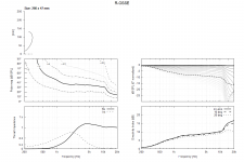
The coaxial arrangement was inspired by a graph from Dmitij_S with a woofer firing behind a sphere simulated earlier in the thread #2,558 .
The green line shows a 10" woofer firing behind a 10" sphere. Looks promising to me for crossover below 1000 Hz. In the end the sphere (or the closed back of the WG) is just a rather smooth dispersion body about half a wavelength in size (path length differences are way smaller).
And a 10" piston will probably be affected more by the sphere than a "ring" of four 5"-pistons.
But I would very much like to be able to simulate my idea. I am not there yet, biting more than I can chew. ;-)
What do you mean by "other sources"? Walls, furniture? Or effects of the speaker surfaces that do not fulfil model assumptions (rigid wall)?Also don't get too upset at the sort of diffractions that ABEC will show, whilst they are no good or desirable, they will in all likelihood be reduced or swamped out by other sources that are not directly modelled. Adding wall impedance to different surfaces is a good way of seeing what might happen if the surface isn't considered to be completely reflective.
So far the measurements shown in the thread seem to match the simulation results pretty well.
It seems like chasing diffraction and back-wave energy is paying off. I made this after getting two fleece blankets form IKEA - 4€ each.
The sound source jumping when moving my head has decreased significantly and clarity but also "calmness" has improved.

Remains how to apply it without looking to corny... as that would be possible to begin with 🙂
//
The sound source jumping when moving my head has decreased significantly and clarity but also "calmness" has improved.
Remains how to apply it without looking to corny... as that would be possible to begin with 🙂
//
Well, yes and no.Have you considered multiple entry horn?
When I first saw MEH ideas I considered this to be overly complex and difficult to get right.
With more examples it is obvious it is a viable idea to get to "quasi-coax" and might work well especially for compact high SPL application.
One of my design goals was to get a small increase of DI from 150 Hz to 10 kHz by using cardioid radiation pattern in LF.
How would you do that with MEH? I do not see how this would work.
So I did not consider it. Another reason is the complexity in acoustics and simulation.
This is what I wanted to try. Might also solve the reflections of the woofer enclosure.It seems like chasing diffraction and back-wave energy is paying off. I made this after getting two fleece blankets form IKEA - 4€ each.
The sound source jumping when moving my head has decreased significantly and clarity but also "calmness" has improved.
View attachment 1130088
Remains how to apply it without looking to corny... as that would be possible to begin with 🙂
//
Can you measure the difference?
- Home
- Loudspeakers
- Multi-Way
- Acoustic Horn Design – The Easy Way (Ath4)