Looks nice! Looking fwd to the individual measurement of the two parts and your reasoning and design of crossover.
//
//
So far I've only attempted to print the few horns upload here. I'm trying to jump into using the program.
I've downloaded the latest (non-beta) version and had previously downloaded version 4.8.0 (though I never did anything with it back then). I'm currently getting the following error in Version 4.8.2, but 4.8.0 works - running the exact same demo1.cfg file.
Any thoughts on what I may be doing wrong?
I've downloaded the latest (non-beta) version and had previously downloaded version 4.8.0 (though I never did anything with it back then). I'm currently getting the following error in Version 4.8.2, but 4.8.0 works - running the exact same demo1.cfg file.
Any thoughts on what I may be doing wrong?
Attachments

... About the awareness, I wrote my post after there where some posts about inspecting 0.25 dB ripple in the FR/DI curves to optimise further when on the other hand hardly any results for complete systems were shown. At least it was my impression...
You guys might consider it funny but I had some serious fun with it 🙂Yes, that was somewhat funny intermezzo 🙂 (but why not)
There is great power with ath (and BEM), anyone can inspect stuff that would be really hard otherwise, roll out small studies like this to get more knowledge, what affects what in the graphs.
Size and shape are connected to complete system design, of course. Results of the sims are visual graphs though, and not sound in the room as part of complete system. I see only fun time ahead, come up with few interesting variations for given system and listen if there is meaningful audible difference to really get some knowledge.
The thing is one can come up with any particular waveguide design and then get it 3D printed with roughly equal amount of work and cost no matter what the shape and response is (as long as size is comparable) so why not try and make it as good as possible? What ever the metric is. Tailor fit to system is best one can do and we are all able to do it with ath. Even for looks! 🙂 I agree diffraction ripple so small is probably not audible and perhaps silly metric to optimize on, but if its a free feature for a system then why not.
Last edited:
Hi, I think it should work fine, size of the waveguide is dictated to fit necessary drivers in so just scale up.... But then the woofers need space and if the spacing between the sources to the sides is too big it is not working any more. And there is the problem of the path length from front to side sources. And for 150 Hz the openings in the WG cannot be too small, even less so with a cardioid that has to push some air....
Distance to sides shouldn't be a problem as you seem to have active cardioid system and delay can be manipulated. Passive cardioid, perhaps. All the side drivers need to do is match sound coming around from the front with suitable delay. If you have nice rollovers and smooth shapes going on it shouldn't be hard in active setup.
System sensitivity would be defined by the cardioid bandwidth so its gonna be low. Size might get too big but still smaller than fullrange MEH. Basically same situation like with any concept with a cardioid mid, sacrificed lows for pattern control.
Devil is in the details so it might turn out the concept really doesn't work. I've prototyped simple plywood box cardioids and experience from that gives me optimism it would work just fine doing actively. Hense I wouldn't rule such design out before checking some more into details.
I have no skills for it either so someone elses task 🙂 just encouraging you not to rule stuff out too early. Of course do what feels interesting to you, most important thing is to have fun with it.
Last edited:
I agree, of course, there's nothing wrong with trying for the best possible. And as we've seen (as you've shown), especially with the lower-DI waveguides there are some pretty feasible options.The thing is one can come up with any particular waveguide design and then get it 3D printed with roughly equal amount of work and cost no matter what the shape and response is (as long as size is comparable) so why not try and make it as good as possible?
You can now try to combine your models with the BEE enclosure, see what you get.
Last edited:
That is the part where experience or understanding helps, the journey there can be a bit bumpy 🙂But then I found out that combining two isolated parts might not work at all the way one would expect it.
The full 3D mesh is more uncertain in general and after a while you can develop an ability to see through it and ignore the artefacts. One of the things I found quite interesting about the original termination style of freestanding guide is that very little sound went behind and when looking at the observation fields it creates something like an "acoustic break". This does a good job of stopping sounds from in front and behind from interfering with each other. That is not so good if you want the sound from behind to make it past the waveguide though. For me this is why I think that having the lower frequency sound exit closer to this termination can still work OK without damaging the waveguide itself too much, but this is still an educated guess.The results for a woofer box beneath a freestanding WG look much more benign, but interference is still obvious and much stronger than most of the differences between different ways of termination or lip form that are frequently discussed here.
The shape of the larger woofer cone should do exactly that and the back of the waveguide can be made to be a volume filler. This could be made to be a fairly close approximation of the four separate chambers I simulated before.In what way do you want to optimise the cavity with a single woofer when the best way to improve the interference seems to be to "fill" the cavity?
As mabat said above they can be managed so the DI is smooth. A larger CTC distance can be a benefit to this if a very small distance is not possible. If it cannot be under 0.5 WL then pushing out to 1.2 to 1.4 WL. This often coincides with the distance between a waveguide and larger driver underneath.About the (vertical) nulls, you might be right, I am a bit obsessed with that. But on the other hand reflection from floor and ceiling are the first ones of the early reflections most of the time and nulls right in the mid range do not seem to be the best idea. Sometimes one reads tips like "use a thick carpet", but I am not yet convinced.
And these nulls are always connected with a DI peak and I am not convinced that those are a good feature either ;-)
You might also want to consider the work of Lipshitz and Vanderkooy who conducted an experiment into the audibility of introduced nulls. Peaks were quite easily heard but nulls could be very deep and not very audible.
Last edited:
I also wanted to point this out but couldn't recall the study. Thanks.... Peaks were quite easily heard but nulls could be very deep and not very audible.
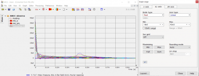
Hi, did you investigate this graph further? I found VACS can export impulse responses but gnuplot goes over my head. To export IR from VACS, first Graph > Convert curves to contour, and then Processing > Fourier response, then right click on the graph and export data.- I just came across this graph, haven't seen this before. It's basically a polar map in the time domain - impulse responses at various angles.
Could it help to visualize something not readily seen in a level map?
View attachment 1129766
http://www.gnuplotting.org/tag/iteration/
I'm not sure if this kind of graph provides valuable info in the end. It would be very interesting to take a look though.
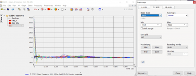
edit. screenshots from VACS showing difference in impulse responses for two waveguides, ST260 and the other is some other profile with backside. Differences show up in the polar maps already but perhaps there is opportunity to compare impulse responses toward listening window or something like that.
Attachments
Last edited:
Not yet and I find the IRs in VACS strange, as they are being shown. I'm not sure how VACS calculates that, maybe a linear frequency step is needed (we typically use log - that can be changed with ABEC.Abscissa=2) - for a regular FFT you need a linear step, maybe VACS re-calculates automatically. And I guess that at least 200 frequencies would have to be solved to get a reasonably long IR, certainly not less than 100. Fortunately, that's still feasible, at least in the CircSym mode. Also, the data must be extended to 0 Hz somehow first, etc. All of it VACS probably does somehow but it's really not that simple.
Perhaps some different transform than the FFT would be even better but I'm not going to dig into that.
Perhaps some different transform than the FFT would be even better but I'm not going to dig into that.
Last edited:
That seems to be the sound traveling around the waveguide. There are two impulses finally meeting at the very back at the same time, that's the peak you see.
Maybe I'll try to implement the IR polar map after all.
Maybe I'll try to implement the IR polar map after all.
Yeah and toward off-axis ~90~180deg there is two like in 135deg, one around each side of the device.
Trying settings
ABEC.NumFrequencies = 256
ABEC.Abscissa = 2
ABEC.f1 = 20
ABEC.f2 = 20000
Trying settings
ABEC.NumFrequencies = 256
ABEC.Abscissa = 2
ABEC.f1 = 20
ABEC.f2 = 20000
Yes, that's what I used. It's best to go through all the IRs interactively.Trying settings
ABEC.NumFrequencies = 256
ABEC.Abscissa = 2
ABEC.f1 = 20
ABEC.f2 = 20000
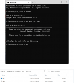
It complains that it can't find the file 'ath.cfg'. Try to copy that from the previous version, obviously it's missing.I can't get ATH 9 prerelease from post 11450 to run like earlier
- With these little updates, I release only the executable file (ath.exe) to be replaced. You still need all the rest from the "baseline installation".
weird, I assumed that it was looking for a config file named ath so I changed the name of my config file to ath, copied it into the directory, and it worked and produced really excellent results using ST260-ROSSE.cfg
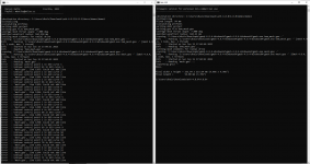
I copied my ath.cfg from version 4.8.3 beta 2, ran it from my path and got a raft of errors.
**************************************************
Error : Unable to recover the edge 26125 (8/31) on curve 688 (on surface 344)
Error : Unable to recover the edge 29525 (1/29) on curve 720 (on surface 352)
Error : Unable to recover the edge 29917 (3/25) on curve 448 (on surface 224)
Error : ------------------------------
Error : Mesh generation error summary
Error : 1914 warnings
Error : 395 errors
Error : Check the full log for details
Error : ------------------------------
Done.
Device width x height = 260.00 x 0.00 mm (10.236 x 0.000")
Device length = 77.70 mm (3.059")
D:\Audio\ATH\ATH-4.9.0>
************************************
my ath.cmd is
OutputRootDir = "D:\Audio\ATH\Horns"
MeshCmd = "D:\Audio\ATH\gmsh-4.7.1-Windows64\gmsh.exe %f -"
GnuplotPath = "C:\Program Files\gnuplot\bin\gnuplot"
I probably missed the errors because I had the cmd window obscured when I ran with my wg's config file named ath.cfg and located in the same directory as ath.exc. Even with the errors, it produced an abec directory which solves cleanly in a few seconds.
Do I need a later gmsh?
Last edited:
- Home
- Loudspeakers
- Multi-Way
- Acoustic Horn Design – The Easy Way (Ath4)