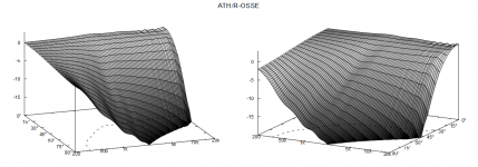
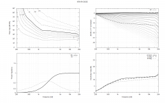
But Tom doesn't have that in his results. Can a slightly smaller arc radius, for example, make such a difference? Maybe it can.Yeah that low frequency DI hump is sound around the device, clearly visible now when diffraction backwave is eliminated with the extra roundover.
- There's a file with the final coordinates generated in the 'Results' directory, called 'coords.txt'. You can use this file to compare different profiles.
The last one has, while ealier one just before doesn't. I'm also curious why the earlier doesn't have such DI hump, hopefully it is not mixed up result attachments but true performance. I believe on the first one without the DI hump the low freq diffraction is balanced, in other words the rollback is sufficiently big to suppress ripple (diffraction backwave) on high frequencies but sufficiently small to leave diffraction backwave on the lows so that sound around device is balanced with the diffraction backwave resulting smooth graph, just like ST260 and others.
Last edited:
can't wait to finish day job and chores to get onto generating some coordinates 😀 so exciting, fun with the hobby 🙂
Last edited:
I need to get some evidence.That's hard to believe but maybe you have something in your script that mixes that up. The on-axis hole definitely emerges with a flat wavefront as the source.
In the meantime, a small change in idea:
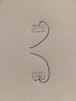
Rollover to 180 deg so on axis is free from ripple. Dump remaining sound in absorber so it doesn't get a chance to influence low frequency DI at high angles.
Unfortunately real-world damping is difficult to model (as I gathered from the previous discussions). Anyway, there's an option to add damping to any element in ABEC in the solving script I think. You would probably have try and measure this in real. Visually, this would be pretty non-obtrusive, should it work.
Wavelength of low frequency anomalies is about diameter of the waveguide, hense the foam block(s) would have to be quite big to be effective, at least 1/4wl in dimension so half R. Or just make the depth of the device similar to R with round shape.. broken record 😀 Well, all tricks are fine, I hope you get good device like that but I suspects only making backsie ~sphere will get really smooth results without side-effects.
Last edited:
I get your point, but where does the sound stay? You can guide it around, but then? You want it gone before it can mess things up.
I'm sorry I don't mean to be rude, I shouldn't write on whim.
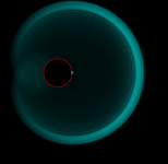
Big enough round shape just redistributes the sound to all directions, no "sharp" corners, no backwave. Problem is the wavelength is long so its hard to get rid of, we can't control its propagation without making the device bigger. Double the diameter to get acoustic features octave down. Better option is to smoothen the shape. Its all relative to wavelength.
Basically, with small rollback on the lip the device outside dimension of depth is "flat" for device diameter sized wavelength. 5cm physical object dimension has almost no effect on 50cm wavelength, it doesn't stop it propagating but acts as relatively sharp corner. I'll simplify a waveguide to a stick in this ripple tank simulation example. Sound diffracts each end of the stick, expands towards opposite end of the stick on both sides and in opposite polarity. To 90 degrees (toward ends of sticks) the wave is propagating opposite polarity on each side and cancel out when they meet again at the other end but not toward listening window.
Listener would be on the right side of this image.
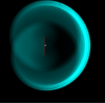
I'm in hurry so demonstrating round back shape with whole sphere, sound goes around "infinitely", no distinct diffraction backwave or secondary sounds making ripple. Basically sound "likes to" expand outwards like a bubble, only small portion of it goes (diffracts) around corners of an object. Some of the sound would go all around the object but only very little and much later as path length around the object here is about 2pi longer moving any interference at least octave down while mellowing them out.
Big enough round shape just redistributes the sound to all directions, no "sharp" corners, no backwave. Problem is the wavelength is long so its hard to get rid of, we can't control its propagation without making the device bigger. Double the diameter to get acoustic features octave down. Better option is to smoothen the shape. Its all relative to wavelength.
Basically, with small rollback on the lip the device outside dimension of depth is "flat" for device diameter sized wavelength. 5cm physical object dimension has almost no effect on 50cm wavelength, it doesn't stop it propagating but acts as relatively sharp corner. I'll simplify a waveguide to a stick in this ripple tank simulation example. Sound diffracts each end of the stick, expands towards opposite end of the stick on both sides and in opposite polarity. To 90 degrees (toward ends of sticks) the wave is propagating opposite polarity on each side and cancel out when they meet again at the other end but not toward listening window.
Listener would be on the right side of this image.

I'm in hurry so demonstrating round back shape with whole sphere, sound goes around "infinitely", no distinct diffraction backwave or secondary sounds making ripple. Basically sound "likes to" expand outwards like a bubble, only small portion of it goes (diffracts) around corners of an object. Some of the sound would go all around the object but only very little and much later as path length around the object here is about 2pi longer moving any interference at least octave down while mellowing them out.

Last edited:
Well, circumference of circle is 2*r*pi so calculting it wrong there, but well, for demonstration purposes why sphere works the post is fine I think. Main take-away is that problems in directivity around 500Hz need solutions whose size is roughly similar, at least quarter to show some effect. 500Hz is roughly 70cm long.
For me the aim is to achieve the best possible results for a given waveguide size. We see that improving one area can easily make something else worse (assuming the sim is not flawed). Fixing that new problem by a 1m sphere is not a solution 🙂
I left thinking your question where does sound stay?I get your point, but where does the sound stay? You can guide it around, but then? You want it gone before it can mess things up.
Short answer is it doesn't, we just have to guide it around and around, or absorb it somehow as you suggest. All relative to wavelength.
Written out, ideal source in simulator emits sound power and function of a waveguide is to concentrate the output power to the listening window reducing it elsewhere. I assume we ideally want to emit sound toward listener to some nominal coverage angle and would like to have very little sound to sides and back. It all relates to wavelength so as our device dimensions are finite, say 50cm, we can have full control on sound whose wavelength is shorter than this, much shorter. At some point wavelength is long enough the device loses control, similar thing as with baffle step. We could use bigger device, or crossover to a bigger one, to extend controlled directivity bandwidth down in frequency. Basically the size is the limiting factor no matter the shape and when size is finite best we can do is to make the shape so that control is lost smoothly.
There is inevitably some limit how low we need to go in practice and it should take account hearing system and situation with room in each case, looks. Its about hunting down the small ripple on graphs and perhaps makes no audible difference so its just fun study.
Definitely not a solution 😀 at least it is not practical so its just interesting path to take and see whats there. No problem to come back to this point, or any earlier points on the ath possibilities exploration graph. You, Tom, maiky76 and many others have posted very good results already, with very little to be gained.For me the aim is to achieve the best results for a given waveguide size. We see that improving one area can easily make something else worse (provided the sim is not flawed). Fixing that new problem by a 1m sphere is not a solution 🙂
Last edited:
Hi
I sent the ST260 stl to JLPCB for printing in resin 8000 model. They ask me to double the thickness of the wall :
"
for enclosures with big size and unoccupied areas parts, have a potential risk of deformation and fracture during the printing and transportation, such as the models could be shrinking to the center and warping to the diagonal lines and edges.
We kindly suggest you to increase the wall thickness to 5.0mm to reduce the risk" "
this is the free standing model, any thougths, please, about that for the ones knowing that resin or company for their prints job ?
So the promised user-defined back side as a cubic Bezier curve:
Mesh.RearShape = 5 ; closed back
Mesh.RearCubic = -60,2,50,-80,5 ; [mm]
https://at-horns.eu/ext/ath-4.9.0-pre-230109-2.zip


You will lose LF directivity this way. To regain, you will probably need to increase the overall size. That's the drawback I see.
Mesh.RearShape = 5 ; closed back
Mesh.RearCubic = -60,2,50,-80,5 ; [mm]
https://at-horns.eu/ext/ath-4.9.0-pre-230109-2.zip
You will lose LF directivity this way. To regain, you will probably need to increase the overall size. That's the drawback I see.
Just an observation - I now got the same garbage from ABEC as you guys before, but only after I set NUC="Dual surface" and restarted the ABEC. It seems that changing this has an effect only after restart. I switched it off again, restarted ABEC and it's all fine again.
- I'm likely going to stick to this approach:


- I'm likely going to stick to this approach:
Last edited:
Could you help me recap which possible solution we have? Since I posted my issue end of November I could not solve it and let things lie idle.
At the time my only change was updating to Win11: https://www.diyaudio.com/community/...he-easy-way-ath4.338806/page-551#post-7189973
1) Is this issue then some behavior of ABEC3 under Win11? Tom, Maiky and fluid could confirm the solving anomalies. However, mabat wrote he was running Win10.
2) AKABAK is not free use, or is it? is using AKABAK a workaround?
3) Do I understand it correctly that turning of NUC=Dual surface in ABEC3 demo preferences and then restarting solved the issue for you, mabat? Was not NUC=Dual surface long time ago recommended in the thread form some other reason? It's been so long I do not fully remember.
Regards
I just love the way this looks regardless of any acoustic benefit/lack thereof
Thank you very much on this 🙂 My results seem to have hair on HF, which is probably due to some other mesh settings, have you had this?So the promised user-defined back side as a cubic Bezier curve:
Mesh.RearShape = 5 ; closed back
Mesh.RearCubic = -60,2,50,-80,5 ; [mm]
https://at-horns.eu/ext/ath-4.9.0-pre-230109-2.zip
View attachment 1128263
View attachment 1128260View attachment 1128258
You will lose LF directivity this way. To regain, you will probably need to increase the overall size. That's the drawback I see.
The same settings work fine without the backside
Without backside
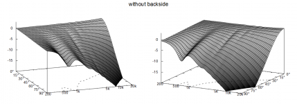
Same script as above but with backside, looks some kind of noise. Any idea which setting could make it? I'll try some other profiles and report if its this one that somehow has it.
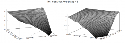
Should look closer to this
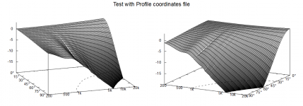
Main visual difference is that the first and last without the noise are open on the back like usual. The new one with noise is closed from the back, probably purposely?
It's strange, now I wasn't able to reproduce the previously clean results for a while, until I activated the NUC again (and restarted ABEC - maybe it's not NUC related at all). Definitely sometimes it calculates it perfectly, sometimes not... That's all I know, I don't have any recap. I haven't tried AKABAK.

- Home
- Loudspeakers
- Multi-Way
- Acoustic Horn Design – The Easy Way (Ath4)
