Any suggestion for a good starting point with a 1.4“ throat so the HF does not narrow too much? Played around with some popular examples from over here (almost all 1“) but cannot get rid of the HF attenuation dtarting at ~12kHz. Of course given by the 1.4“ source…but besides slotted throat there are other attempts to overcome this? The wave-former feature would be a good approach?
Been away for a while.
My only suggestion would be to make the overall beamwidth narrow enough so that the source related narrowing at HF is not too severe. That requires a large device but that's something you always want anyway. The wave-former feature would be a good solution if it worked - it does on paper but working practical examples are still to be seen.Any suggestion for a good starting point with a 1.4“ throat so the HF does not narrow too much?
Last edited:
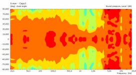
BTW, I'm working on a new design - 18" woofer in an open baffle with a large waveguide with 1.5" driver:
Horizontal, vertical (only):


Horizontal, vertical (only):

Cool. I can hear (I think) the directivity clash between a wide LF and a narrow HF in my Hornflowers. No catastrophe but its there alright...
//
//
Hi to all!
First post there, is there a CFG for ath of the ST260B ?
as I want to simulate with a dome but i can find only the STL Abec Project.
First post there, is there a CFG for ath of the ST260B ?
as I want to simulate with a dome but i can find only the STL Abec Project.
same similar question. It seems the abec project files that Mabat has so kindly provided are the same for ST260 and ST260B which of course isn't right. A cfg file for the ST260/260B would be great because then we could look at directivity with it in a box on a baffle next to a woofer.
Hi to all!
First post there, is there a CFG for ath of the ST260B ?
as I want to simulate with a dome but i can find only the STL Abec Project.
https://www.diyaudio.com/community/...-design-the-easy-way-ath4.338806/post-6914654
The size of the driverWhich parameter affect mostly the band between 16k to 20k?
Many thanks.
As fluid said, the source diameter.Which parameter affect mostly the band between 16k to 20k?
Many thanks.
Apart from that: A low parameter os.k increases HF loading within the boundaries of the source, and vice versa. (OS-SE formula)
Many thanks, I actually solved it messing with the parameters, such a good tool!
Throat.Diameter = 25.5
Throat.Angle=24
Throat.Profile = 1
Coverage.Angle = 45.3
OS.k = 0.34
Length = 62.5
Term.s = 1.55
Term.n = 3.65
Term.q = 0.996
Source.Shape = 1
Source.Curv = 0
Source.Radius = 20
Source.Velocity = 2
ABEC.MeshFrequency = 60000
ABEC.NumFrequencies = 300
ABEC.SimType = 1
ABEC.SimProfile = 1
ABEC.f1 = 500
ABEC.f2 = 20000
ABEC.Polars:SPL = {
MapAngleRange = -90,90,19
Distance = 2m
NormAngle = 0
Offset=63mm ;
}
Output.ABECProject = 1
Output.STL = 1
That's my config for a 1" dome waveguide and simulated good in ABEC3.
My question is, why if I open the generated STL is ten times bigger than the waveguide original measures?
Is it a matter of scale or should I simulate it again?
From CMD seems good.
TERMINAL
-destination directory: C:\Horns\260B
-circular symmetry mode for profile 1
-initializing
-fixed length: 62.5 mm
-calculating profiles
-writing ABEC project
-final mesh average throat angle: 24.000 deg
-using fixed wavefront radius: 20 mm
-running 'C:\gmsh-4.6.0-Windows64\gmsh.exe mesh.geo -'
Info : Running 'C:\gmsh-4.6.0-Windows64\gmsh.exe mesh.geo -' [Gmsh 4.6.0, 1 node, max. 1 thread]
Info : Started on Wed Aug 31 00:50:37 2022
Info : Reading 'mesh.geo'...
Done.
Final width x height = 280.7 x 280.7 mm (11.052 x 11.052")
Final length = 62.5 mm (2.461")
Many thanks in advance to anyone could help!
I would definitely take a couple of these. 😉 As always, very nice work.BTW...with 1.5" driver:
Horizontal, vertical (only):
View attachment 1085424 View attachment 1085425
Is the horn proprietary or will you make the parameters available?
What are the dimensions?
Best wishes
David
You have simulated a spherical cap with axial motion which is not the most realistic way to simulate a dome. Using the Source.Contours options to include a surround, better dome approximation and driving weights would give a different result.That's my config for a 1" dome waveguide and simulated good in ABEC3.
STL files are unitless, the software opening them has to be set to the right scale for them to be the correct size. Ath makes STL's in mm so the viewing software needs to be the same, at 10 times the size that would suggest it is set to cm.My question is, why if I open the generated STL is ten times bigger than the waveguide original measures?
Is it a matter of scale or should I simulate it again?
Simulating it that way will give you a false sense of reality, domes behave very differently to each other but they can be simulated quite successfully with the Source.Contours settings at least up until 10K or so, where beyond that all bets are off, because the underlying assumptions in the simulation vary from reality. For the same reason hard domes are more likely to behave as predicted than soft domes.I tought that a dome was a pistonic movement with a spherical cap for a first approximation, unfortunately i don't have the measurements of a 1" dome.
There is an example in the appendix, you cold use that for a start.
I have no intentions at the moment. Some day I may be selling the plans, I don't know - as it is, it's an adapter attached to a bended board construction.I would definitely take a couple of these. 😉 As always, very nice work.
Is the horn proprietary or will you make the parameters available?
What are the dimensions?
Best wishes
David
I don't recall exactly but it's something like 25" x 18" x 13" (WxHxD).
That was mainly as an example what to expect from a 1.5" throat regarding the HF directivity. There seems to be no way (except a diffraction slot) to avoid the directivity index to reach ~15 dB around 15 kHz. What can be controlled, however, is how to get there and what's below.
I checked now and the files at https://at-horns.eu/ST260.html are correct.It seems the abec project files that Mabat has so kindly provided are the same for ST260 and ST260B which of course isn't right.
It's not so hard to make your own 🙂A cfg file for the ST260/260B would be great because then we could look at directivity with it in a box on a baffle next to a woofer.
To this day, I haven't really heard the ST260... Sad, isn't it.
Quite a few of the previous (pre-Ath) generation. There yet wasn't a chance to listen to a finished project employing the latest techniques - they are still evolving, faster than I'm able to make actual loudspeakers 🙂
Last edited:
Good Morning.
excuse my ignorance. I really want to learn about how to extract polar predictions from waveguides. I work with hornresp and I'm starting with axidriver. I did some co projects (solid edge), my question is:
-is it possible to import guides (horns) made in solid edge to software like akabak or axidriver?
- Home
- Loudspeakers
- Multi-Way
- Acoustic Horn Design – The Easy Way (Ath4)