
Despite the limited depth, this one should facilitate a crossover between roughly 500 and 700 Hz, depending on the driver.I gave that one a try too.
Code:R-OSSE = { R = 204.4463 ; [mm] r0 = 25 ; [mm] a0 = 0 ; [deg] a = 33.3064 ; [deg] k = 2.5606 + 3.2955*sin(1*p)^5.0417; [] r = 0.28838 ; [] b = 0.11572 ; [] m = 0.86488 ; [] q = 5.8055 ; [] }
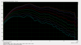
Note: the dynamic range of the normalized polars is 30dB vs 45dB
Again, trying to find solutions in the vicinity (size and coverage) of the starting point.
View attachment 1051586
I am curious, what the expected advantages of the asymmetrical profile?
-C-C for X0ver in not one of them (still circular mouth)
-Smoothness does not seem to be as good both from simulation POW and from the direct comparison showed by @Dkalsi
-On-axis smoothness by breaking the symmetry? But smoothness ON can be made rather aceptable through optimization.
-Different H and V coverage angles but at the expense of the “constant” characteristic
Last edited:
That holds for any 2" driver on virtually any device.this one should facilitate a crossover between roughly 500 and 700 Hz, depending on the driver.
And here is the horizontal polar (20-40-60) comparison of the ST260 vs ST260B (again utilizing the Peerless DFM-2535R00).
The ST260B was not baffle mounted (as it should have been). I'm only sharing these measurements to highlight the improved smoothness the rollback contributes to the design. I'm sure, if the ST260B was baffle mounted into a cabinet with large roundovers, it would have similar results to the ST260 measurements.
The ST260B appeals to me because it allows one to utilize the volume behind the horn for the LF driver.
Attachments
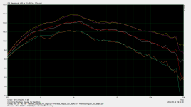
Thanks. What strikes me the most is the difference above 16 kHz. Hard to comprehend why is that. The ST260 is more "textbook" but clearly worse. Is that the same driver (i.e. the same piece)?comparison of the ST260 vs ST260B
Last edited:
Yes - the exact same part. If there is something suspect, I wonder if it has to do with the less than ideal print of the ST260 (because it's two pieces that are merely taped together). The ST260B was 100% successful print job and was printed as one piece (i.e., no glue-ups/tapes).Thanks. What strikes me the most is the difference above 16 kHz. Hard to comprehend why is that. The ST260 is more "textbook" but clearly worse. Is that the same driver (i.e. the same piece)?
Also - I think Peerless DFM-2535R00 itself exhibits a drop-off above 16Khz per its spec sheet. Thus, I'm inclined to believe the ST260 remains "textbook", but perhaps the unmounted ST260B is adding (noise?) something above 16Khz.
What could be a reason why for 1/2 symmetry gmsh fails to mesh, while with the very same settings, in 1/4 symmetry everything is fine?
I have checked box dimesions and distances and this does not seem to be a reason.
Error : 'bem_mesh.geo', line 554: Unknown variable 'nan'
I have checked box dimesions and distances and this does not seem to be a reason.
mabat - what did you mix the brass powder with to make it stick to the ST260 that you painted?
//
//
Without the code it's impossible to say.What could be a reason why for 1/2 symmetry gmsh fails to mesh, while with the very same settings, in 1/4 symmetry everything is fine?
I used XTC-3D but it makes quite viscous and fast setting mixture, not very comfortable to work with on larger surfaces. I still want to try some other resins as I really like the finish.mabat - what did you mix the brass powder with to make it stick to the ST260 that you painted?
Without the code it's impossible to say.
Code:
Throat.Profile = 1
Throat.Diameter = 25.4
Throat.Angle = 10.08
Length = 76.1
Coverage.Angle = 47.399064  + -16.037475 * sin(1*p)^1.8199468
OS.k = 0.45  + 0.3 * sin(1*p)^1.9909458
Term.s = 2.0891155 + -0.042002443 * sin(1*p)^2
Term.n = 3.7354139 + 0.4411222 * sin(1*p)^1.9810752
Term.q = 0.88199313 + -0.0044746989 * sin(1*p)^1.9994829

Source.Shape = 1
Source.Curv = 0
Source.Radius = -1
Source.Velocity = 1

Mesh.Enclosure = {
Spacing = 27,30,27,367 ; edge distances
Depth = 270 ; enclosure depth
EdgeRadius = 25 ; radius of the edge treatment
EdgeType = 1
FrontResolution = 15,15,20,20
BackResolution = 20,20,30,30

 LFSource.Below = {
    Spacing = 60
    Radius = 106.5
    DrivingWeight = 1
 }
}

Mesh.InterfaceResolution = 8.0
Mesh.LengthSegments = 30
Mesh.AngularSegments = 48
Mesh.ThroatResolution = 5
Mesh.SubdomainSlices =
Mesh.ZMapPoints = 0.5,0.1,0.76,0.733

;Mesh.Quadrants = 14Guys, you don't listen to me. You have to use absolute values of the sines:
Otherwise it's like division by zero, you just can't do that.
(For some reason fabs() doesn't work, so use abs() instead.)
Code:
Coverage.Angle = 47.399064 + -16.037475 * abs(sin(p))^1.8199468
OS.k = 0.45 + 0.3 * abs(sin(p))^1.9909458
Term.s = 2.0891155 + -0.042002443 * sin(p)^2
Term.n = 3.7354139 + 0.4411222 * abs(sin(p))^1.9810752
Term.q = 0.88199313 + -0.0044746989 * abs(sin(p))^1.9994829
Otherwise it's like division by zero, you just can't do that.
(For some reason fabs() doesn't work, so use abs() instead.)
Last edited:
I'm slowly progressing with the big one. This is the first one, the second one should already be an easy matter after I finally found this perfect jig -


BTW, the "petals" are hollow near the edges and are connected (and aligned) with inserted ribs, also a very effective approach:

BTW, the "petals" are hollow near the edges and are connected (and aligned) with inserted ribs, also a very effective approach:
Last edited:
Could you explain some more mabat? E.g. what about the screw? What makes it the perfect jig? ...?
It holds everything in place and auto-aligned. The screw is fastened to the plywood base.


Are you filling the petals? If so at what stage - before or after assembly? And with what?
//
//
Does the PU adhere chemically well to the printed pa? Or do you need mechanical interlocking (rough surface; printed mini-hooks;….). At least this kind of PU has minor shrinkage….
That holds for any 2" driver on virtually any device.
This is indeed true for most horns. Most drivers with 2" exit and 4" diaphragm should reproduce 500 Hz even without a horn, but certainly not without problems - including possible damage, at higher SPLs.
Personally, I wouldn't (want to) use a 2" driver from 500 Hz with a short horn like this:
- Home
- Loudspeakers
- Multi-Way
- Acoustic Horn Design – The Easy Way (Ath4)