I gave that one a try too.Just for the record, 2" throat, ⌀400 x 250 mm:
View attachment 1048279
H, V (0 - 90/5)
View attachment 1048280 View attachment 1048281 View attachment 1048282
Code:R-OSSE = { R = 200 r0 = 25 a0 = 0 a = 33 k = 3 + 5*sin(p)^2 r = 0.35 b = 0.12 m = 0.83 q = 4.4 }
Code:
R-OSSE = {
  R  = 204.4463 ; [mm]
  r0 = 25 ; [mm]
  a0 = 0 ; [deg]
  a  = 33.3064 ; [deg]
  k  = 2.5606 + 3.2955*sin(1*p)^5.0417; []
  r  = 0.28838 ; []
  b  = 0.11572 ; []
  m  = 0.86488 ; []
  q  = 5.8055 ; []
         }
Note: the dynamic range of the normalized polars is 30dB vs 45dB
Again, trying to find solutions in the vicinity (size and coverage) of the starting point.
I am curious, what the expected advantages of the asymmetrical profile?
-C-C for X0ver in not one of them (still circular mouth)
-Smoothness does not seem to be as good both from simulation POW and from the direct comparison showed by @Dkalsi
-On-axis smoothness by breaking the symmetry? But smoothness ON can be made rather aceptable through optimization.
-Different H and V coverage angles but at the expense of the “constant” characteristic
Hello,I thought they made interface to simplify ADAU+Sigma Studio.
I can share or made to/for you some Sigma config for ADAU1707 if you want.
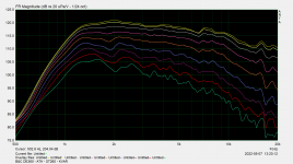
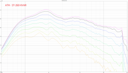
Do you still have the raw non-normalized data?Here are horizontal polar measurements of the ST260 vs ST260-KVAR
That's guaranteed with the curves exported from Ath. The last time I did it I was surprised how smoothly it went.Fusion is very picky about rails they must intersect each profile/slice precisely.
As you said before sometimes it works when you loft a section at a time but not all in one go. I've had the same trouble with curves I've made myself where they do intersect but the order in which they are selected seems important it getting the loft to function. Then other times there is no problem at all.That's guaranteed with the curves exported from Ath. The last time I did it I was surprised how smoothly it went.
Actually, the notion that an asymmetry is needed to improve on-axis smoothness has been proved false a long time ago. There's no problem getting an exemplary smooth response even with an axisymmetric device. That has been settled I think.-On-axis smoothness by breaking the symmetry?

If there was a sharp peak in the impedance (or any abrupt change), the frequency response would be affected by that - there would be a sharp peak as well. And a sharp peak in FR has a longer decay in time response/CSD. The same holds for the response of the driver (and the response combined). There's really no resonance induced by the horn acoustic impedance that you wouldn't see in the amplitude frequency response (if measured properly).I would be interested if there the correlation between simulated acoustic impedance and resonances can be drawn or not.
Last edited:
Just a remark -
sin(p)^5.0417 (in maiky's code) is not a legitimate mathematical operation - it would need to be fabs(sin(p))^5.0417.
sin(p)^5.0417 (in maiky's code) is not a legitimate mathematical operation - it would need to be fabs(sin(p))^5.0417.
Just a remark -
sin(p)^5.0417 (in maiky's code) is not a legitimate mathematical operation - it would need to be fabs(sin(p))^5.0417.
Thanks for pointing that out although I am quite sure what you mean.
What issue is it causing? sin and x^y are both defined, aren't they?
From the numerical optimization POW the only important point is that one input always yields the same output.
I am not familiar with the LUA language you are using, I checked the doc before making the optimizer but I could not find any details on the way the functions are behaving and C99 should work or throw an error.
I would assume that in Ath either NaN or +/-∞ would throw an error or cause the design to be nonsensical, I might be wrong.
When I tried I did not get any error and the design looks "normal" so I assumed that the function would drop the imaginary part or ignore what it did not like. Is that the case?
I gave that one a try too.
Maiky, could you try an improvement with your optimization script on this baffled waveguide in quarter symmetry? My goal was a 'wide' pattern of about 50 degrees at HF, beginning even a little wider in the lower frequencies, and a slightly sloping DI. The latter I realized through the vertical axis.
Results for quarter symmetry / half symmetry:


The current dimension is 265 x 200 mm, where the width is defined by the intended baffle. The vertical dimension I had found to be a good trade off for the intended goal, tho reduce vertical dimension, yet retain vertical pattern control. The term q was used to set the vertical dimension, this is why it has so many digets. I wonder if the dip between 1.000 and 2.000 Hz could be solved better, that shows up in the horizontal plane, and if the ripple could be further smoothened.
Quarter symmetry results translate quite well into hald symmetry, final box, so quarter sym can be used for optimization (quarter symmetry <-> hald symmetry):
hor


ver


Code:
; ____ Parameters ____
Throat.Angle = 10.08
Throat.Diameter = 25.4
Throat.Profile = 1
Coverage.Angle = 50 -9*sin(p)^2
Length = 66.5
Term.s = 2.3 -0.05*sin(p)^2
Term.n = 3.4 +0.4*sin(p)^2
OS.k = 0.45 +0.3*sin(p)^2
Term.q = 0.87674 -0.00425*sin(p)^2
; ____ Source Mode ____
Source.Shape = 1
Source.Curv = 0
Source.Radius = -1
Source.Velocity = 1
; ____ Enclosure ____
Mesh.Enclosure = {
Spacing = 27,30,27,338 ; edge distances (left,top,right,bottom) [mm]
Depth = 270 ; enclosure depth [mm]
EdgeRadius = 25 ; radius of the edge treatment [mm]
EdgeType = 1 ; 1=rounded, 2=chamfered
FrontResolution = 8,8,16,16 ; front side mesh element size (q1,q2,q3,q4) [mm]
BackResolution = 20,20,20,20 ; back side mesh element size (q1,q2,q3,q4) [mm]
}
; ____ 3D Mesh Settings ____
Mesh.InterfaceResolution = 8.0
Mesh.LengthSegments = 30
Mesh.AngularSegments = 48
Mesh.ThroatResolution = 3
Mesh.SubdomainSlices =
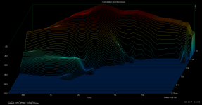
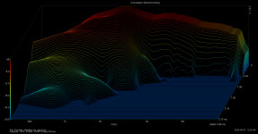
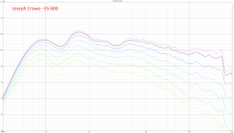
Mesh.ZMapPoints = 0.5,0.1,0.76,0.733Sorry, I missed this. Yes - please find attached non-normalized data (as well as other random measurements: (i) CSD of ST-260KVAR (ii) CSD of ST-260, (iii) H-Polars of B&C DE360 on ST-260-KVAR, and (iv) H-Polars of the Peerless on Joseph Crowe ES-800 Radial Horn).Do you still have the raw non-normalized data?
Attachments
-
 Peerless ATH - ST260 - CSD - 10 Deg Off Axis.png171.4 KB · Views: 177
 -
 Peerless ATH - ST260 - KVAR - CSD - 10 Deg Off Axis.png200.6 KB · Views: 173
 -
 B&C DE360 - ATH - ST260 - KVAR - Raw.png40.6 KB · Views: 340
 -
 Peerless Polars - ATH - ST260 - KVAR - Raw.png346.2 KB · Views: 171
 -
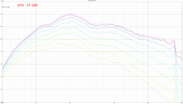 Peerless Polars - ATH - ST260 - Raw.png887.7 KB · Views: 175
 -
 Peerless Polars - Joseph Crowe ES-800.png782.2 KB · Views: 184
Has anyone compared CSD vs. polar? I never seen that... does the CSD look different between 0 and say 30 deg?
//
//
Thank you, that's a nice comparison. I quite like the KVAR mutation.Yes - please find attached non-normalized data
What is a bit surprising to me is that at HF both the non-KVAR and the KVAR ST260 produce virtually the same SPL on-axis, including the slope of the response, although the KVAR has (should have) more beaming pattern vertically. So I would expect the KVAR to be a little bit more flat but that's not what's happening - curious. Maybe the vertical beamimg is still too mild to have a substantial effect.
Last edited:
As the CSD is a different look at a (single) impulse respone, it will be different in different directions, correspondingly to how different are the IRs. Basically, all resonances should be present at the same frequencies in all directions - that's the typical behaviour and also how we recognize resonances from a set of polars.Has anyone compared CSD vs. polar? I never seen that... does the CSD look different between 0 and say 30 deg?
Last edited:
Apologies if there's a dedicated bug reporting space where this belongs, but I think I've found a bug with 4.8.2. when modeling complex sources, ATH throws the error "the 1d mesh seems not to be forming a closed loop", and the middle of my dome doesn't get meshed - this applies even to the example dome file from page 40 of the manual, and to custom dome configurations that work fine in 4.8.0.
I think this has been fixed already: https://www.diyaudio.com/community/...-design-the-easy-way-ath4.338806/post-6996527
Ahh, so it has! Sorry, I was just using the latest version from https://at-horns.eu/, so I didn't see the beta version.I think this has been fixed already: https://www.diyaudio.com/community/...-design-the-easy-way-ath4.338806/post-6996527
2 weeks ago I told another member that it won't be long before we see ATH4(inspired) loudspeaker systems and,
lo and behold...

lo and behold...
Last edited:
- Home
- Loudspeakers
- Multi-Way
- Acoustic Horn Design – The Easy Way (Ath4)