
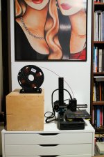
Looking great, Marcel.
Btw, I impulse-purchased the same printer you’re using to get these wonderful prints. Are you using the machine as it is setup out of the box or have you made any upgrades I should know about?
Btw, I impulse-purchased the same printer you’re using to get these wonderful prints. Are you using the machine as it is setup out of the box or have you made any upgrades I should know about?
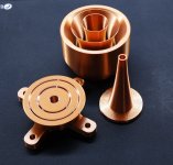
No upgrades, only the nozzle was replaced for the 0.25 Bondtech - Bondtech Brass Nozzle M6x1x5x13 1.75 for MK8 compatible 3D printers
Attachments
Indeed. This is the way of the future, but more importantly I'm excited to see the results.
Not so long ago, the last external phase plug I made I cast the cone in polyester, which eased the surround due to the heat produced. Then inserted rods and used a dremel to work through it. I hadn't simmed it, just conventional design methods so I wasn't even sure what to expect. They took weeks to finish... now with simpler methods we are bound to improve by doing.
Not so long ago, the last external phase plug I made I cast the cone in polyester, which eased the surround due to the heat produced. Then inserted rods and used a dremel to work through it. I hadn't simmed it, just conventional design methods so I wasn't even sure what to expect. They took weeks to finish... now with simpler methods we are bound to improve by doing.
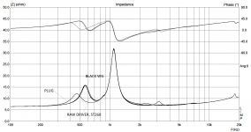
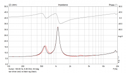
BTW, what can be said already (if anything), observing the lower impedance peak? This is a comparison of four different setups - raw driver, black wg, ST260, new plug.
- ST260 waveguide has virtually no effect
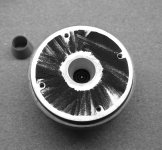
- the new plug shifts the peak lower and makes it more damped
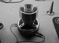
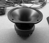
- with the "black wg" (see the photo) the peak shifts a tiny bit higher (?!)
The driver is FANE CD131.
- ST260 waveguide has virtually no effect
- the new plug shifts the peak lower and makes it more damped
- with the "black wg" (see the photo) the peak shifts a tiny bit higher (?!)
The driver is FANE CD131.
Attachments
Something seem to happen 2250Hz as can be also seen in #8882 but due to the b/w pic it cant be traced above but I suppose it still is the plug?
//
//
That's not very interesting at this point as those are various resonances caused by the lack of a proper termination. I expect that with a horn it will be much cleaner.
Last edited:
Yes, that's the main reason. I want to try various drivers and this size seems to be the easiest to begin with.
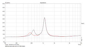
Disregard the previous graphs, I must have mixed it up.BTW, what can be said already (if anything), observing the lower impedance peak? This is a comparison of four different setups - raw driver, black wg, ST260, new plug.
I measured the impedances again, this time it should be correct -
Attachments

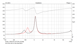
I measured the impedances again, this time it should be correct -
There are two peaks because it is a coupled system, just like a ported enclosure. The null indicates the resonance of the coupled system (like the ported box resonance,) each peak represents the individual resonances - waveguide mass to gap compliance and diaphragm to gap compliance. The gap compliance is the coupling between the two masses. In your examples, the null lowers as does the waveguides resonance indicating that a significantly increased mass loading is presented to the system by the new design. The driver's peak does not change.
Is there a more intuitive description of "mass loading"? What it is in the context of horns and how to imagine it...
Is that so more of the air is pushed in one direction (as in PWT)?
Is that so more of the air is pushed in one direction (as in PWT)?
Last edited:
I don't know if this is a more intuitive description for you, but the mass loading is closely related to the radiation reactance of any radiator. If the reactance is positive, then it is said that it adds mass, if it is negative then it is said that it adds compliance. The greater radiation reactance is, the greater loading mass is.
The manifestation of radiation reactance itself is somehow related to the problem of spherical divergence of the acoustical wave.
The manifestation of radiation reactance itself is somehow related to the problem of spherical divergence of the acoustical wave.
So in the PWT there's no mass loading as there's no reactance.
So the mass loading is effectively an amount (mass) of air that just moves with the source as a whole?
So the mass loading is effectively an amount (mass) of air that just moves with the source as a whole?
Last edited:
Yes, probably it is the most intuitive difinition of of the added mass. Here is the picture from Kinsler et al. - Fundamentals of Acoustics that explains how reactance is related to the added mass in the case of flat piston radiation.

Last edited:
That is a good illustration, of what is going on Mabat!
I suppose that the impedances of the fanes are well matched, otherwise there would have been artefacts in the impedance response higher up in frequency where the air wouldn't be just moving back and forward with the source.
I suppose that the impedances of the fanes are well matched, otherwise there would have been artefacts in the impedance response higher up in frequency where the air wouldn't be just moving back and forward with the source.
Honestly, I don't have a clue, maybe that's not even a requirement (and I would doubt they are matched). For example, changing the area ratios of the channels (i.e. moving the positions of the vanes) virtually doesn't change the acoustic impedance of the throat (so neither the electrical impedance, I assume).
- If I studied acoustics it would be far more fun now for me I guess 🙂
- If I studied acoustics it would be far more fun now for me I guess 🙂
Last edited:
- Home
- Loudspeakers
- Multi-Way
- Acoustic Horn Design – The Easy Way (Ath4)