Has anybody tried acoustically measuring the effective exit angle of a compression driver, and could give some pointers?
I can't help as I haven't gone very far with that myself yet 🙂
In the light of some of the recent discussions I'm not even sure it would work as I intended.
It's actually a pretty difficult thing to do.
In the light of some of the recent discussions I'm not even sure it would work as I intended.
It's actually a pretty difficult thing to do.
I believe it would be.
Are you planning to incorporate your external phase plug into Ath for printing, and can it be adjusted for entry angle?
Are you planning to incorporate your external phase plug into Ath for printing, and can it be adjusted for entry angle?
Yes, it will be available, I'm working on just that. It can be adjusted for entry angle.
Perhaps optical means could be used to visualize the wavefront shape?I believe it would be.
I don't know, maybe some acoustical jig could be designed and printed that would allow to measure the wavefront directly at several points when attached to the driver - some sort of a grid of channels/horns that would lead from different places of the wavefront to points where a mic could be attached without disturbing the initial wavefront a lot?
Maybe even something as the external phase plug? We can simulate these things and perhaps could derive the actual source shape from measured results, based on the differences from the sims.
Maybe even something as the external phase plug? We can simulate these things and perhaps could derive the actual source shape from measured results, based on the differences from the sims.
Last edited:
To get an idea of how the waveform propogates, how about using some form optical setup? Just thinking this of the top of my head: compression driver in a clinical environment and using the driver to propell some form of dust via an impulse response. And by using some kind of reflective/backlit light to film how the waveform propogates through the dust.
And no, I have no idea what I'm talking about 🙂
And no, I have no idea what I'm talking about 🙂
Seems to be the same problem as the graphs not having the correct names for the reports to find them
Acoustic Horn Design – The Easy Way (Ath4)
It looks like the file "di.txt" is required by the graphing program of ATH, and Abec isn't generating "di.txt"
What is strange is that it was working before; I have projects from a few months ago where "di.txt" was generated properly.
I'm stumped.
Check if your polar map contains angles 0, 10 and 20 deg, which is what is needed for the file DI.txt to be written by Ath.
It works in 4.7.2, please download the latest version (there was a bug in 4.7.0)
Hello Mabat, I first thank you for the update, I can indeed combine the GCurve and Morph features now.
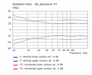
The specifications of my project are to obtain a horn with a square mouth of dimensions 250x250mm maximum. I want a constant directivity of 60x40° (Horizontal x Vertical planes) between 2 kHz and 16 kHz.
Thanks to the GCurve and Morph features I can almost obtain what I want (first picture), but in the vertical plane I'm losing directivity control way too early, i.e from about 5-6 kHz. I would like the vertical directivity pattern to be always below the horizontal one, but on the picture you can see between 2 and 4 kHz it is the opposite.
I tried a lot of different parameters settings (mainly s, q, n variations) but it can barely lower the frequency where I lose directivity control.
But I also found out that the low frequency loss of directivity control is f = K/(Θ × d) with:
f : low frequency loss of directivity control (horizontal or vertical)
Θ : coverage angle (horizontal or vertical)
d : mouth dimension (horizontal or vertical)
K : constant
So as I want a coverage angle of 40° in the vertical plane, I understand that I have to maximize my vertical mouth dimension to lose directivity control as low as possible, but I can't increase the vertical dimension, I am already at the maximum, and I can't change the coverage angle either.
Do you think there is another way to lower this low frequency loss of directivity control ?
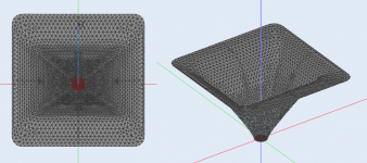
(I attach my script and screenshots of my horn for information)
Attachments
wenz56,
the apparent loss of directivity might be a result of the virtual mounting of the waveguide device on an infinite baffle in ABEC. This has been discussed earlier. One solution to test what directivity could be achieved is connected to a lot of effort and knowledge in ABEC: create a virtual enclosure. fluid did this, he told us it was a tedious task.You can disable the infinite baffle, but this will create strong diffraction effects.
I would also love to study the effect confidently, but we would need virtual enclosures for this. I currently use a waveguide which is 29 cm wide and it does control the pattern easily down to your crossover frequency, but, and here comes my doubts, this waveguide has no termination or put another way, uses most of its wall length for pattern control. Ath uses a good part for termination and I think this will also reduce pattern control, albeit for a much smoother response.
Your waveguide, then again, does seem to utilize not too much of wall length for termination, I think you should be good.
That's solely up to the user, it's possible to create abrupt terminations as well (not that it brings any advantage).... Ath uses a good part for termination and I think this will also reduce pattern control, albeit for a much smoother response.
- It's simply not possible to create a small waveguide that controls narrow beam down to very low frequency. Or at least I don't know of a way how to do it.
Last edited:
Check if your polar map contains angles 0, 10 and 20 deg, which is what is needed for the file DI.txt to be written by Ath.
Thanks!
I was using nine degree increments, that's probably the issue then.
Sorry for that, that's something that remained hard coded in the software and this error not properly handled.
- Home
- Loudspeakers
- Multi-Way
- Acoustic Horn Design – The Easy Way (Ath4)