Thanks, I wasn‘t understanding what reversed normals was meaning.
It‘s not the actual Mesh though, but maybe the problem is also existent in the ABEC project (attached in #7999), got to check it after the night shift is over.
It‘s not the actual Mesh though, but maybe the problem is also existent in the ABEC project (attached in #7999), got to check it after the night shift is over.
Last edited:
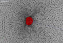
If the mesh is already corrupted that way, it doesn't make much sense to correct the few utterly bad elements. The only proper solution is to generate a better mesh (as I said, reducing the number of Mesh.LengthSegments usually helps and it was already OK in the attached mesh, however still too dense around the slots). I'm only afraid I can't reproduce it anymore as I continually develop and tweak the Ath version I'm using. So perhaps a next release will be more robust in this regard.
BTW, I'm preparing a release with a support of LE driver model, showing also the diaphragm excursion and resulting electrical impedance on the driver terminals. This should bring some light into the discussions about how horn loading helps or not.
BTW, I'm preparing a release with a support of LE driver model, showing also the diaphragm excursion and resulting electrical impedance on the driver terminals. This should bring some light into the discussions about how horn loading helps or not.
Last edited:
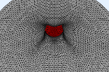
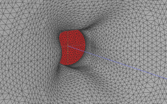
I have to admit, I do not understand why the response beyond 15 kHz is so rough. I checked the mesh of the actual waveguide for reversed normals and there where none, as said, the picture above was only an illustration with a finer mesh for more features. Did decrease length segments, increased them in another step, to no success.
Last edited:
Do you have the NUC functionality activated in ABEC preferences? I noticed I have it set to "Dual surface", maybe that also helps a bit. But definitely your mesh is still not in a good shape (too many too narrow triangles) as I get the same results when I try it. Maybe that's just how the released Ath version handled slots in the mesh (i.e. pretty poorly), I don't remember. With my current version of Ath I have locally on my PC these problems are gone. But it's not yet ready to be released, there are still problems I need to fix.
Last edited:
3D meshes are more prone to issues with numerical instability producing garbage, at very high frequencies the mesh needs to be very fine and well constructed to avoid problems. In the cirsym mode the mesh frequency can be super high and still not take much time making the high frequencies nice and clean in the simulation.I have to admit, I do not understand why the response beyond 15 kHz is so rough.
If the solution is resolution, it is fine. I can let the machine calculate a day if this means at the end I see something reasonable. But I am confused, because I thought reducing resolution of the mesh was the advice. With mesh length slices 30 instead of 50 or so and mesh angular resolution 40 instead of 80, also NUC=true placed in solver file, the result is still garbage (see attached). Maybe I will leave it with that for now and focus on the circular devices.
For the circular device, I tried to eyeball the directivity extension of the -6 dB threshold and came up with something like 2-2.5°/oct. The measurements of the Dayton H6512 seem to indicate a widening from 20 kHz to 1.25 kHz by 10 degree. That would be 2.5°/oct again. I hope to guestimate what the polar pattern looks like at the crossover, to come to a good design target. Comments on this doubtful method are welcome.
For the circular device, I tried to eyeball the directivity extension of the -6 dB threshold and came up with something like 2-2.5°/oct. The measurements of the Dayton H6512 seem to indicate a widening from 20 kHz to 1.25 kHz by 10 degree. That would be 2.5°/oct again. I hope to guestimate what the polar pattern looks like at the crossover, to come to a good design target. Comments on this doubtful method are welcome.
Attachments
The number of length segments ("slices") and the mesh resolution are independent and it's good to know the difference - see page 16 of the current User Guide
Yes,I kept the resolution parameter as is (1000) and only changed length slices and later also angular.
Sorry for the sloppy use of terms here. I understood the guide in that mesh resolution is the possibility of connections, while length/angular slices is actually defining the size of the triangles. Only changed the slices parameter.
Sorry for the sloppy use of terms here. I understood the guide in that mesh resolution is the possibility of connections, while length/angular slices is actually defining the size of the triangles. Only changed the slices parameter.
Last edited:
Maybe you try to be too precise here. Due to the smooth decrease of the DI, it should not be too hard to match the directivities at the crossover, provided both are roughly the same in that region. Simply any waveguide of these qualities of about the size of the woofer should work, IMHO.For the circular device, I tried to eyeball the directivity extension of the -6 dB threshold and came up with something like 2-2.5°/oct. The measurements of the Dayton H6512 seem to indicate a widening from 20 kHz to 1.25 kHz by 10 degree. That would be 2.5°/oct again. I hope to guestimate what the polar pattern looks like at the crossover, to come to a good design target. Comments on this doubtful method are welcome.
That's yet another different resolution 🙂 So there are in fact three kinds of resolutions. It may be confusing to a newcomer, I admit.Yes,I kept the resolution as is (1000) and only changed length slices and later also angular.
When I say resolution I really mean edge length of the triangles as that is what limits the validity of the data at high frequencies.Yes,I kept the resolution parameter as is (1000) and only changed length slices and later also angular.
Sorry for the sloppy use of terms here. I understood the guide in that mesh resolution is the possibility of connections, while length/angular slices is actually defining the size of the triangles. Only changed the slices parameter.
The mesh resolution (1000) determines if ABEC will remesh to reach the desired resolution. This is unlikely with any reasonable settings in Ath if 1000 is used.
Reducing the number of length segments does help, you should only use enough to ensure the mesh is the right shape and hasn't been changed away from what you intended. Adding more "resolution" here can be counterproductive and make bad meshes.
When making the edge length small that will increase the number of elements in the simulation. When this gets above 5000 the simulation will take a long time 10 to 12 hours. When it gets to 10,000 often ABEC will go into a sort of endless loop where there is no answer to be found and it keeps wailing at it forever and never finishing.
In other words check the number elements before running the sim and walking away as too much brute force resolution may not work.
Also some of the smoothly terminated waveguides are picky about the interface used and trying different types gives different results.
Also some of the smoothly terminated waveguides are picky about the interface used and trying different types gives different results.
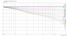
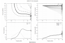
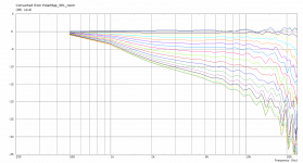
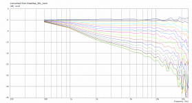
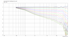
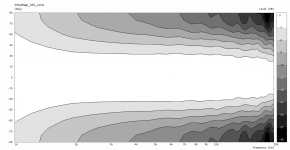
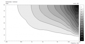
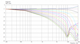
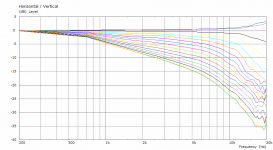
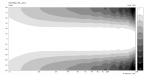
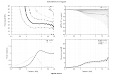
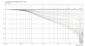
I removed the interface offset and that was all it needed. These are some off the results. To me, the wiggles look like actual resonances. The trade-offs compared to a non-slotted throat seem quite obvious, two throat treatments competing for the same limited surface area, directivity control vs loading/extension. And added resonance. I used Slot.Length with the paramter 5, 8 and 10*cos(2*p)^2 to see the effect (graphs in this order).
Attachments
-
 waveguide10.png106 KB · Views: 124
 -
 waveguide8.png105.6 KB · Views: 134
 -
 waveguide5.png107.4 KB · Views: 142
 -
 spl_norm10.png42.3 KB · Views: 149
 -
 spl_norm8.png41.7 KB · Views: 321
 -
 spl_norm5.png41.8 KB · Views: 318
 -
 sono10.png56.7 KB · Views: 318
 -
 sono8.png54.8 KB · Views: 400
 -
 sono5.png57.2 KB · Views: 403
Last edited:
Marcel
I agree with you that the idea of mis-shaping the throat is to throw in some decorrelation of the wavefront to smooth out problems. My thought was to make the perturbations axisymmetric rather than the other way. A small ripple in the contour might just do the same thing, but easier to model. At any rate, I would love to see what effect this has. Small ripples, like a wavelet packet, would not be seen at Lower f's but at some frequency, most likely when the wavelengths match, it should be pronounced. A more random shape may work more broadband - like tire treads.
I agree with you that the idea of mis-shaping the throat is to throw in some decorrelation of the wavefront to smooth out problems. My thought was to make the perturbations axisymmetric rather than the other way. A small ripple in the contour might just do the same thing, but easier to model. At any rate, I would love to see what effect this has. Small ripples, like a wavelet packet, would not be seen at Lower f's but at some frequency, most likely when the wavelengths match, it should be pronounced. A more random shape may work more broadband - like tire treads.
This hasn't occurred to me. It sounds like an easy experiment - will try. In the meantime, just for a case of success, you can invent a name for it - that's often the hardest part 🙂
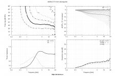
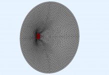
This is a "slotted" throat for a 2" driver. I must say it looks almost usable (for a 2" throat).
Waveguide ⌀368 x 108 mm, infinite baffle.
Waveguide ⌀368 x 108 mm, infinite baffle.
Attachments

In the meantime, just for a case of success, you can invent a name for it - that's often the hardest part 🙂
The "tickler."
I tried to optimize for a smooth, both in frequency and directivity extended and controled HF response, with a smooth overal frequency response. I do not know if with further studying, the resonances can be surpressed better. The pattern width is now comparable to a CE360 baffled, I could not get wider because as with the cicular symmetry devices, I approached a lower limit with the paramter OS.k. This time not at 0.75, but below 0.68, where ath was reporting a number of "nan" lines and could not properly mesh with gmsh. Also, I could not increase length segments over 20 with the current settings, same "nan" reports, but could have increased angular to high numbers (used 40).
Attachments
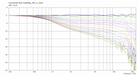
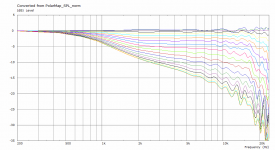

Above 10K this has the look of numerical instability making that data unreliable.To me, the wiggles look like actual resonances.
The slots mabat simulated didn't have this problem, maybe if he runs some "tickler" sims it will give a better idea what is going on.
- Home
- Loudspeakers
- Multi-Way
- Acoustic Horn Design – The Easy Way (Ath4)