I'll see what I can do regarding the sharing of my work on the optimization framework.
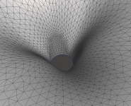
- I still wonder about the quite abrupt onset of the DI rise above 15 kHz in all these axisymmetric waveguides. With a 1" driver this is probably mostly academic but with bigger drivers this still troubles me (and in fact, it may be actually better with a real world driver than with an ideal wavefront). After all, it may not be a bad idea to add some kind "slot" into the throat. If smooth and "random" enough, perhaps it could distribute the higher order stuff to become less obtrusive, I don't know. I already tried someting and it looked promising. Some aspects will be undoubtely worse, someting may improve. Maybe someone could try as well - of course you have to switch to the full 3D mesh calculation.
In the latest version of Ath you can easily define a slot, which is just a conical extension of the throat:
; 2 + 25 mm = max. slot length (2 mm minimum)
; 2 slots
Slot.Length = 2 + 25*cos(p)^2
; 3 slots
Slot.Length = 2 + 25*cos(1.5*p)^2
; 4 slots
Slot.Length = 2 + 25*cos(2*p)^2
To keep the mouth circular simply add:
Morph.TargetShape = 2
Unfortunately the tool doesn't properly handle a rollback with non-axisymmetric shapes, so it's better to try it with an infinite baffle.
Attachments
Last edited:
Maybe someone could try as well - of course you have to switch to the full 3D mesh calculation.
I'm not entirely sure if that is true. If I use any sine/cosine function within circular symmetry mode, ath console tells me different height/width values. Morph.TargetShape = 2 does then lead to a console report that seemingly shows a symmetrical device, but I can still see different axial response if I tell ABEC to show the axes separately in VACS ('hidden' in the ath report). Now I do not know if the results are correct, but the slots still seem to get calculated in a way in cicular symmetry mode. Changing the mode to mesh then shows what is hidden beneath the graphical interface.
Is OS.k = 0.75 minimum value for this parameter? Below, my waveguide collapses to a flat disk.
Reports of a rework of the 50-degree device from #7960. Set aside the question, whether or not a wider radiation pattern is actually desireable, I am satisfied with the implementation. With 68 mm length, the device is quite flat, comments welcome.


JBL seems to prefer 100° radiation patterns with their latest products (4349, 708, M2). I for myself must say that sadly, I cannot place the speakers as wide apart as I would want them to stand. If I overstretch the stereo triangle, heavy toe in of 45° does sound great, but I could not leave the room no more because the door would be blocked then 🙂. That is too bad because the center of my current speakers is so solid, it does actually benefit from a wider then text book positioning. If they are closer, heavy toe in does reduce the size of the image. Maybe this is the (bad) reason why I started to investigate a wider radiation pattern.
JBL seems to prefer 100° radiation patterns with their latest products (4349, 708, M2). I for myself must say that sadly, I cannot place the speakers as wide apart as I would want them to stand. If I overstretch the stereo triangle, heavy toe in of 45° does sound great, but I could not leave the room no more because the door would be blocked then 🙂. That is too bad because the center of my current speakers is so solid, it does actually benefit from a wider then text book positioning. If they are closer, heavy toe in does reduce the size of the image. Maybe this is the (bad) reason why I started to investigate a wider radiation pattern.
Circular symmetry uses a single profile, so it might include part of the slot but it would then be calculated the same all the way around. If there is a mesh it is 3D, in circsym there is one profile rotated all the way around in steps.I'm not entirely sure if that is true. If I use any sine/cosine function within circular symmetry mode, ath console tells me different height/width values. Morph.TargetShape = 2 does then lead to a console report that seemingly shows a symmetrical device, but I can still see different axial response if I tell ABEC to show the axes separately in VACS ('hidden' in the ath report). Now I do not know if the results are correct, but the slots still seem to get calculated in a way in cicular symmetry mode. Changing the mode to mesh then shows what is hidden beneath the graphical interface.
Hi,
Is there a way to feed real measurements of a CD or tweeter to ATH so that the model of the waveguide/horn reflects the real performance on that CD/tweeter in particular?
If measuring a CD, should I measure it first without any horn/waveguide?
Is there a way to feed real measurements of a CD or tweeter to ATH so that the model of the waveguide/horn reflects the real performance on that CD/tweeter in particular?
If measuring a CD, should I measure it first without any horn/waveguide?
You would need a plane wave tube I assume. I have one but have never tried this, actually.Hi,
Is there a way to feed real measurements of a CD or tweeter to ATH so that the model of the waveguide/horn reflects the real performance on that CD/tweeter in particular?
If measuring a CD, should I measure it first without any horn/waveguide?
As fluid said, in the CircSym mode you explicitly specify one profile (via "ABEC.SimProfile") that is effectively revolved around the axis and that makes an axisymmetric device. For anything non-axisymmetric you have to switch to full 3D simulation (i.e. omit "ABEC.SimProfile" and set the grid/mesh properly).I'm not entirely sure if that is true. If I use any sine/cosine function within circular symmetry mode, ath console tells me different height/width values. Morph.TargetShape = 2 does then lead to a console report that seemingly shows a symmetrical device, but I can still see different axial response if I tell ABEC to show the axes separately in VACS ('hidden' in the ath report). Now I do not know if the results are correct, but the slots still seem to get calculated in a way in cicular symmetry mode. Changing the mode to mesh then shows what is hidden beneath the graphical interface.
It can't be negative, but other values should work. If it collapses, something else must be the cause, IMO.Is OS.k = 0.75 minimum value for this parameter? Below, my waveguide collapses to a flat disk.
Short answer no, longer answer yes if you have a klippel laser scanner, then you can import a vibration analysis file to augment the other driver models.Hi,
Is there a way to feed real measurements of a CD or tweeter to ATH so that the model of the waveguide/horn reflects the real performance on that CD/tweeter in particular?

From the older discussions I learned that you can measure velocity profile on a PWT and then use that to drive the throat in simulation. I only don't remember how high in frequency this works - probably for the fundamental mode only.
If that's what you want I think you couldn't do better.Reports of a rework of the 50-degree device from #7960. Set aside the question, whether or not a wider radiation pattern is actually desireable, I am satisfied with the implementation. With 68 mm length, the device is quite flat, comments welcome. ...
There is the Def_MeasRadiator option where an SPL and Impedance needs to be provided but it doesn't seem like it is intended for being used as a driver model.From the older discussions I learned that you can measure velocity profile on a PWT and then use that to drive the throat in simulation. I only don't remember how high in frequency this works - probably for the fundamental mode only.
From the manual
ABEC does process velocity-distributions with the help of section VibFile
Currently, VibFile supports files, which are exported by the Klippel laser-scanner software
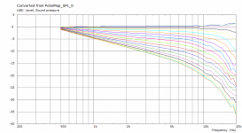
What can be done to have a better judgement of the -6 dB pattern at low frequencies? I find it hard to understand how fast it is rising and to what degree. An unbaffled device like CE360 seems to fall by 10 degree from 20 to 1 kHz, but they seem to tighten up a bit more in the HF than a baffled device.
edit: The DI report is sound power DI, correct? Does the fact that a baffled device is simulated only up to 90 degrees lateral change the graph? Or is it generally comparable with spin data from other speakers?
edit: The DI report is sound power DI, correct? Does the fact that a baffled device is simulated only up to 90 degrees lateral change the graph? Or is it generally comparable with spin data from other speakers?
Last edited:
Sorry, I don't fully understand the first question.
As for the DI, it will be around 3 dB (?) lower in an infinite baffle than full space. I'm sure there's some explanation for this, I'm just too lazy to think about it at the moment (provided my calculation is correct for the half space, I never checked, actually). It's not directly comparable to a finite baffle situation.
As for the DI, it will be around 3 dB (?) lower in an infinite baffle than full space. I'm sure there's some explanation for this, I'm just too lazy to think about it at the moment (provided my calculation is correct for the half space, I never checked, actually). It's not directly comparable to a finite baffle situation.
Say I want to optimize the waveguide to match a 12-inch woofer. While the - 3 dB curve is only changing direction abruptly between 1 and 2 kHz and one can assume that on a baffle, the pattern will more or less continue, the - 6 dB curve is more obscure. It is changing earlier, faster and is getting very wide because of the infinite baffle. Usually the - 6 dB threshold is taken to determine the pattern width of a waveguide, but I cannot really 'see' it at a frequency where it is most important: at the crossover. Can this be mitigated?
Good to know about the 3 dB increase!
Good to know about the 3 dB increase!
You can simulate a 12" woofer under the same conditions (e.g. via the Source Definition Script in Ath). It won't be totally accourate because a real diaphragm will probably flex and change its directivity near the upper end of the passband but as a first pproximation it's probably better than nothing.
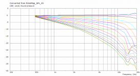
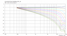
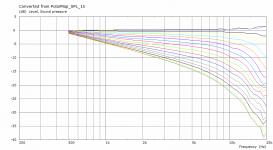
This is an example: CE360 modified for 1.4" throat (36 mm), mounted in an infinite baffle (i.e. no rollback). For the modified (non-axisymmetric) throat four polar sets are shown, for different inclination angles: 0 (=horizontal), 15, 30, 45 (=diagonal), the rest is symmetrical. If anything, it doesn't do any harm it seems. The throat impedance is also a little higher (not shown).I still wonder about the quite abrupt onset of the DI rise above 15 kHz in all these axisymmetric waveguides. With a 1" driver this is probably mostly academic but with bigger drivers this still troubles me [...] I already tried someting and it looked promising.
Attachments
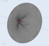

STL file of the surface.
(I believe this is what they are really doing with the M2 throat - distributing these effects in the throat in space and time.)
(I believe this is what they are really doing with the M2 throat - distributing these effects in the throat in space and time.)
Attachments
Last edited:
Maybe "slots" is not the right term, that's just how a named the functionality in the software. The throat is not narrowed anywhere. Basically, the exit section of the driver doesn't stop at one plane but in a "crown" shape. Then a usual waveguide profle starts from there.
"Horn loudspeaker" from Wikipedia....
Most popular constant directivity horns (also known as CD horns) suffer from non-spherical wave fronts, limitations in array ability, distortion at high sound pressure levels as well as reflections and distortions related to the transition from diffraction slot to secondary horn.
Dr Geddes gets a mention at the OSWG section...
Last edited:
Well here it's not a diffraction slot (otherwise you would have to call any driver-horn junction as a diffraction slot, unless the horn was purely conical).
- Home
- Loudspeakers
- Multi-Way
- Acoustic Horn Design – The Easy Way (Ath4)