It's hard to say whether it will work noticeably with a real driver. In the raw data of the M2 the same narrowing above ~ 12kHz is still obvious: https://dl.dropboxusercontent.com/s/8ungqonpzx19ir4/SPL Horizontal.png?dl=0
Last edited:
Is this all code used for the HF loading, but with much lower values?
I wanted to try if this does any good for 1"-CDs, but mesh optimization is quite a bit slower and I could not find working values within reasonable time. My current wageduide Dayton H6512 actually shows the same basic behaviour as the device from #7963, it falls of sharply at 15 kHz. But the loading grooves introduce a peaking at 18 kHz and extend the HF up to 19 kHz.
Code:
Slot.Length = 2 + 25*cos(2*p)^2
Morph.TargetShape = 2
I wanted to try if this does any good for 1"-CDs, but mesh optimization is quite a bit slower and I could not find working values within reasonable time. My current wageduide Dayton H6512 actually shows the same basic behaviour as the device from #7963, it falls of sharply at 15 kHz. But the loading grooves introduce a peaking at 18 kHz and extend the HF up to 19 kHz.
Attachments
Sometimes I find it difficult to understand your queries. The motivation here was to mitigate the sudden drop in SPL off-axis, as I believe that a sudden change is never a good thing. If it also "improves" the loading somewhat, it's only a by-product.
If it works at all, it will work for any throat size the same, only in a different frequency range (proportionally).
With the modified CE360 script, I think I settled on Slot.Length = 2 + 20*cos(2*p)^2 for a 1.4" throat.
If it works at all, it will work for any throat size the same, only in a different frequency range (proportionally).
With the modified CE360 script, I think I settled on Slot.Length = 2 + 20*cos(2*p)^2 for a 1.4" throat.
Last edited:
I perfectly understand that. Sometimes, I write in reversed order, sorry for that. My message consisted of an observation and a question: The Progressive-Transition waveguides of JBL, that where an advancement from Keele's original 2344, show the same sharp decline at around 15 kHz, as the OSSE-waveguides do. The 'only' thing they add is a peaking at 18 kHz. They do not perform essentially different in HF and I was surprised this is the whole story. Secondly, the question not properly spelled out was how I would find reasonable start values for 1"-CD HF-loading slots, because finding them by chance is time consuming in mesh mode. 2 + 20-something gave me very odd results. But you probably do not now either and I will see another time if it is worth to work it out.
Last edited:
No, I really don't know. I would expect it has to be a length comparable to wavelengths involved, but perhaps not much longer. The good thing is that you don't have to simulate a large waveguide as it's all HF stuff.
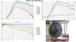
Almost a year ago Pet007 (a fellow hobbyist) designed waveguide with a similar throat (at the time by a different mechanism in the software but quite close). I didn't pay much attention then, I contributed the HF results mainly to the driver (B&C DE502) but maybe the throat does its job as well (see the smooth DI rise between 10 - 20 kHz).
This was only 9" wide.
This was only 9" wide.
Attachments
Last edited:
All right, I now found also a measurement of what was a predecessor of the ST260 and it's virtually the same. So perhaps the throat is not the cause 🙂
From these data it would seem that real-world drivers actually perform better than what the simulation shows for an ideal wavefront...
From these data it would seem that real-world drivers actually perform better than what the simulation shows for an ideal wavefront...
Attachments
The idea is to more evenly distribute/spread their origin in space and time as you can't avoid them (unless you have a source of a pure spherical wave).
Last edited:
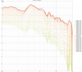
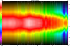
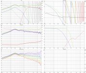
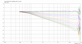
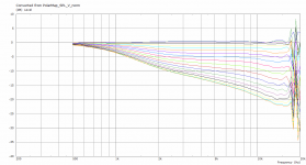
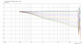
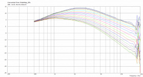
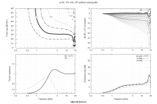
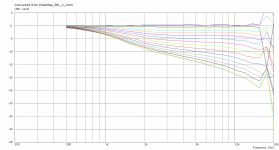
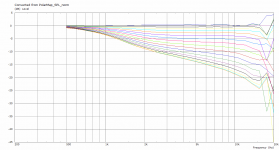
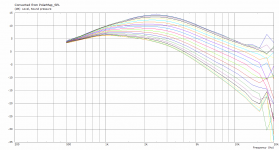
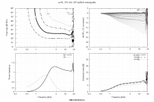
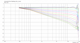
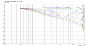
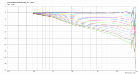
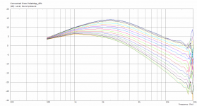
I gave it a shot and started from the axisymmetric devices I generated before. This is why the dispersion got a bit narrow due to my standard optimization process. I could set up a device first that will not narrow down so much after optimization. Anyway, here are some images for a baffled device 315 mm diameter, 90 mm length.
Same device, but the first series of graphs is coarse with
Mesh.LengthSegments = 30
ABEC.NumFrequencies = 30
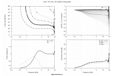
the second fine with
Mesh.LengthSegments = 80
ABEC.NumFrequencies = 100
and solving time of 45 minutes. The difference is quite pronounced.
edit:
Slot.Length = 1 + 10*cos(2*p)^2
Same device, but the first series of graphs is coarse with
Mesh.LengthSegments = 30
ABEC.NumFrequencies = 30
the second fine with
Mesh.LengthSegments = 80
ABEC.NumFrequencies = 100
and solving time of 45 minutes. The difference is quite pronounced.
edit:
Slot.Length = 1 + 10*cos(2*p)^2
Attachments
-
 norm_d2.png38.5 KB · Views: 124
 -
 norm_v2.png38.2 KB · Views: 115
 -
 spl_norm2.png38.1 KB · Views: 117
 -
 spl2.png45 KB · Views: 142
 -
 waveguide1.png109.7 KB · Views: 419
 -
 norm_d1.png36.3 KB · Views: 416
 -
 norm_v1.png36 KB · Views: 415
 -
 spl_norm1.png35.8 KB · Views: 415
 -
 spl1.png42.6 KB · Views: 429
 -
 waveguide2.png119.5 KB · Views: 145
Last edited:
Oh, you have too sparse mesh for 20 kHz. Set also Mesh.ThroatResolution = 3, that should help a lot (I have Mesh.MouthResolution omitted, the default is 8 mm, IIRC). If you set also ABEC.Abscissa = 2 you will have linear frequency step, then you can reduce the number of frequencies to 20 - 40 and still have sufficienty high sampling of the data in the top octave.
Mesh.LengthSegments = 80
Mesh.ThroatResolution = 3.0 ; [mm]
Mesh.InterfaceResolution = 9.0 ; [mm]
Mesh.InterfaceOffset = 5.0 ; [mm]
ABEC.MeshFrequency = 1000
ABEC.NumFrequencies = 30
ABEC.Abscissa = 2
Which values need to be further increased? I will hit F5 then and show results tonight.
Mesh.ThroatResolution = 3.0 ; [mm]
Mesh.InterfaceResolution = 9.0 ; [mm]
Mesh.InterfaceOffset = 5.0 ; [mm]
ABEC.MeshFrequency = 1000
ABEC.NumFrequencies = 30
ABEC.Abscissa = 2
Which values need to be further increased? I will hit F5 then and show results tonight.
This is the whole script I used.
Code:
Throat.Angle = 2
Throat.Diameter = 36
Throat.Profile = 1
Coverage.Angle = 41.91
Length = 107.7
Rollback = 0
Rollback.Angle = 180
Rollback.Exp = 1.5
Rollback.StartAt = 0.585
OS.k = 1.30
Rot = 0
Slot.Length = 2 + 20*cos(2*p)^2
Term.n = 4.03
Term.q = 0.996
Term.s = 1.32
Morph.TargetShape = 2
Source.Shape = 2
Mesh.AngularSegments = 80
Mesh.LengthSegments = 32
Mesh.RearShape = 1
Mesh.InterfaceOffset = 4
Mesh.WallThickness = 6
Mesh.ThroatResolution = 3
ABEC.MeshFrequency = 1000
ABEC.NumFrequencies = 40
ABEC.SimType = 1
ABEC.Abscissa = 2
ABEC.f1 = 500
ABEC.f2 = 20000
ABEC.Polars:SPL_0 = {
MapAngleRange = 0,90,19
Distance = 2 ; [m]
Inclination = 0
Offset = 110
NormAngle = 10
}
ABEC.Polars:SPL_15 = {
MapAngleRange = 0,90,19
Distance = 2 ; [m]
Inclination = 15
Offset = 110
NormAngle = 10
}
ABEC.Polars:SPL_30 = {
MapAngleRange = 0,90,19
Distance = 2 ; [m]
Inclination = 30
Offset = 110
NormAngle = 10
}
ABEC.Polars:SPL_45 = {
MapAngleRange = 0,90,19
Distance = 2 ; [m]
Inclination = 45
Offset = 110
NormAngle = 10
}
Output.ABECProject = 1
Output.STL = 0
Report = {
Title = "ATH CE360-S"
Width = 1200
Height = 800
NormAngle = 10
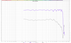
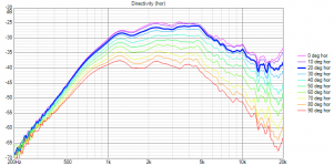
}It's always a pleasure to repeat the measurement of the Sandhorn (1" throat, normalized to 10 deg) 🙂
This is the axisymmetric throat.
- Maybe the exit wavefront of this driver (HF108) is so clean that it matches the general simulation so well, who knows.

This is the axisymmetric throat.
- Maybe the exit wavefront of this driver (HF108) is so clean that it matches the general simulation so well, who knows.
Attachments

Last edited:
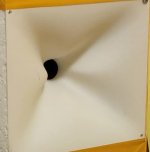
Same device with the above Mesh settings lend from mabat, picture of throat with different Mesh
Attachments
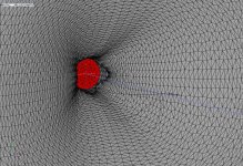
Hmm, that's still not all correct. It seems there are some elements with reversed normals, maybe too many slices. If you upload the ABEC project, I can try to figure out what's wrong. It's up to you. Try to decrease the number of length segments.
Otherwise I think it does some good, doesn't it.
Otherwise I think it does some good, doesn't it.
Last edited:
What makes you think there still is an error? I will fiddle some more with it the coming days until I reach a result that satisfies me. ABEC folder is attached. The Mesh values used in ath are:
Mesh.LengthSegments = 32
Mesh.AngularSegments = 80
Mesh.ThroatResolution = 3
Mesh.InterfaceOffset = 5.0
ABEC.MeshFrequency = 1000
ABEC.NumFrequencies = 40
ABEC.Abscissa = 2
ABEC.SimType = 1
ABEC.f1 = 500
ABEC.f2 = 20000
Whether it does good might depend on the question if the actual response of a waveguide + compression driver combination is not already more extended than what the simulated waveguide response suggests. What about the sandhorn? If so, it is unreasonable to add complexity. In any way, the VHF act like an supertweeter casting sound chaoticly to disperse it. That means if the CD does something comparable with a axisymmetric device, there is nothing gained in here. But I would prefere if the actual response is not cut-off at 15 kHz. I will prepare two similar devices in the next weeks, one with slots, but begin to print with the axisymmetrical. Maybe it is unneccesary with a 1"-compression driver, these slots. Real measurements got to show. But until I gain access to the printer, I might have to wait a bit.
Attachments
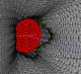
You've got holes in your mesh because some of the triangles are turned the wrong way round, that is the Reversed Normals. Sometimes this happens with mesh generation, you need to identify which tags need to be swapped and correct the tags in the solving script.
That is at least part of what is causing the spiky HF response in the simulation.
This post shows the problem and how you can fix it
Acoustic Horn Design – The Easy Way (Ath4)
I've highlighted in green the holes that are visible, rotate the mesh and should be easier to see from behind

That is at least part of what is causing the spiky HF response in the simulation.
This post shows the problem and how you can fix it
Acoustic Horn Design – The Easy Way (Ath4)
I've highlighted in green the holes that are visible, rotate the mesh and should be easier to see from behind
Attachments
- Home
- Loudspeakers
- Multi-Way
- Acoustic Horn Design – The Easy Way (Ath4)