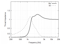
That's just tied to the amplitude response, i.e. there's simply a resonance somewhere inside the driver.
That's the diaphragm resonance - surprisingly low damping for a compression driver.
Here's another measurement of the HF1440 I forgot about.
https://www.diyaudio.com/forums/multi-way/336505-hf1440-ring-compression-driver-faital-pro-20.html#post6620372
https://www.diyaudio.com/forums/multi-way/336505-hf1440-ring-compression-driver-faital-pro-20.html#post6620372
Thanks. So we want a horn with throat impedance peaking just above the fundamental driver resonance, don't we. Damn, this calls for a lumped-element model of the driver.
Last edited:
AS you might expect, the coupling of the elements around resonance can get complex and unintuitive. Models are usually required.
But at these L(ish)Fs the waveguides impedance looks like a simple mass. The dual humps in the electrical impedance curve are due to the coupled oscillator defined by the gap compliance and the two masses - waveguide and diaphragm. At the lower impedance you have the two masses in phase and the above peak they are out of phase, i.e. 180 degree phase shift. This coupling makes the whole problem much more complex.
But at these L(ish)Fs the waveguides impedance looks like a simple mass. The dual humps in the electrical impedance curve are due to the coupled oscillator defined by the gap compliance and the two masses - waveguide and diaphragm. At the lower impedance you have the two masses in phase and the above peak they are out of phase, i.e. 180 degree phase shift. This coupling makes the whole problem much more complex.
This evening my friend Jokerbre and i measured Peerless DFM2535R00-08 on Mabat's ST260 waveguide.
Measurements are done from 1m distance with calibrated Behringer ECM8000, Steinberg UR12 and gate frequency of 4.4ms so enough to capture trends of this waveguide. What is shown here are measurents 0-90 degrees with ≈7.5 deg increments in between. Since i did not calibrate REW and my mic for loudness, SPL levels shown aren't representative of actual SPL level. Off axis measurements 60 degrees and up are smoothed 1/48 to avoid "hair" at higher frequencies.
0-90 degrees

0-45 degress

45-90 degrees

75dB vs 85dB loudness

measurement on axis (red) and averaged 0-90 degrees (purple)

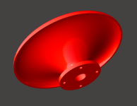
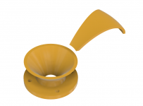
printed waveguide


I must say that i've never seen better and more extended frequency response from a smaller waveguide and a cheaper compression driver.
Measurements are done from 1m distance with calibrated Behringer ECM8000, Steinberg UR12 and gate frequency of 4.4ms so enough to capture trends of this waveguide. What is shown here are measurents 0-90 degrees with ≈7.5 deg increments in between. Since i did not calibrate REW and my mic for loudness, SPL levels shown aren't representative of actual SPL level. Off axis measurements 60 degrees and up are smoothed 1/48 to avoid "hair" at higher frequencies.
0-90 degrees
0-45 degress
45-90 degrees
75dB vs 85dB loudness
measurement on axis (red) and averaged 0-90 degrees (purple)
printed waveguide
I must say that i've never seen better and more extended frequency response from a smaller waveguide and a cheaper compression driver.
Last edited:
Very nice indeed. Nice looking print quality as well.
Same quality of directivity results I measured with a different driver, BMS 4552nd. ST260 is a killer little waveguide.
Such good directivity I am left wondering what would be a good match below.
Side by side 8s and a 15 below is one thought.
Same quality of directivity results I measured with a different driver, BMS 4552nd. ST260 is a killer little waveguide.
Such good directivity I am left wondering what would be a good match below.
Side by side 8s and a 15 below is one thought.
I have a pair of FaitalPro 12pr320-8 i must spend somehow.
0.2mm nozzle with 20% infill.
Very nice indeed. Nice looking print quality as well.
0.2mm nozzle with 20% infill.
Last edited:
A 12" is "the other" option I have considered but I always like to complicate things for myself... That 12pr320 you have is a nice nice NICE option!
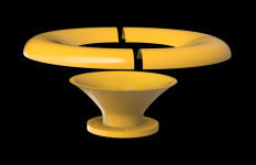
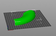
Maybe this could be a way of printing it with minimal warping.
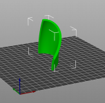
For even larger horns it could the the throat section + "petal" pieces of the rest, printed one by one diagonally across the print bed. Could be tedious to put it all together, that's the drawback.
For even larger horns it could the the throat section + "petal" pieces of the rest, printed one by one diagonally across the print bed. Could be tedious to put it all together, that's the drawback.
Attachments
Last edited:
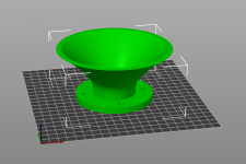
As even the smaller printers can do 250 - 270 mm diagonally across the bed, I guess it could be pretty big, actually, like 15" at least.What is the maximum dimensions this way? My printer is tiny . . .
A good thing about this approach would be that a one failed print doesn't mean doing it all again.
An actual object optimized for this approach could be made a lot more sturdy/massive, of course, especially around the main joint. But it wouldn't be particularly cheap either if made in a print shop, I'm afraid. Someone would have to try.
Last edited:
Ok, I wasn´t too clear with the question..
I meant the ST260. My printer does ca. 150mm(D)x250mm(W)x170mm(H).
I meant the ST260. My printer does ca. 150mm(D)x250mm(W)x170mm(H).
- Home
- Loudspeakers
- Multi-Way
- Acoustic Horn Design – The Easy Way (Ath4)