I've figured that out. The workaround at the moment is to not let q = 1, but always slightly smaller (0.995 is fine).
Thank you!
I don't know if it's the best way but this is how I would do it:
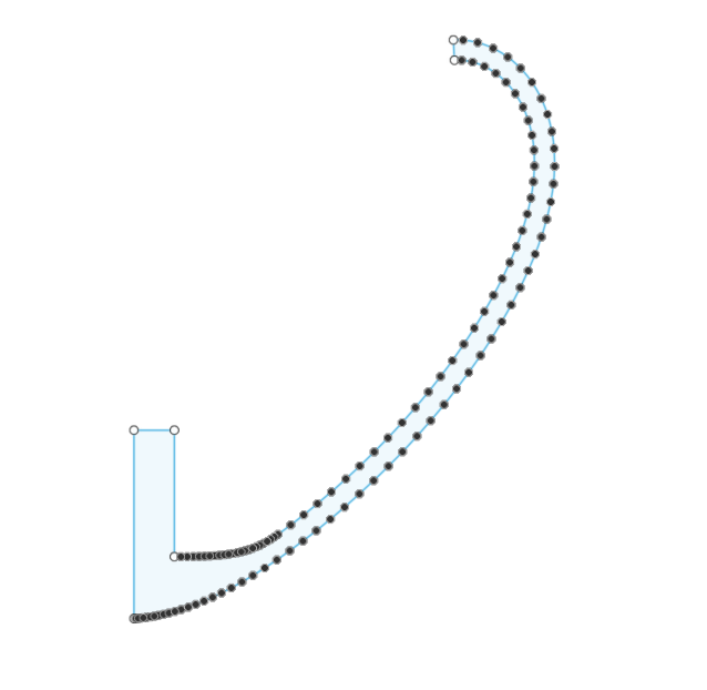
1) Use this undocumented (yet) feature of Ath, which creates an *.afp file:
2) Import the *.afp file into Autodesk Fusion 360 with the attached Add-In.
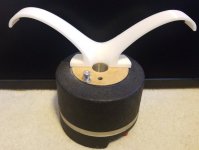
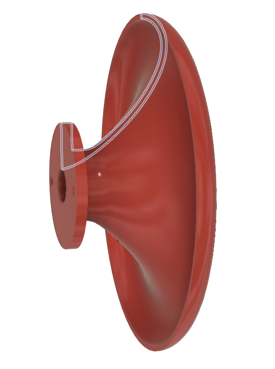
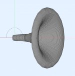
3) Make it solid by revolving it around the X axis and cut the holes...
4) Export as STL and print.
This all takes no more than about 2 minutes (not the printing part 🙂).
1) Use this undocumented (yet) feature of Ath, which creates an *.afp file:
Code:
FusionRotaryProfile = {
  Thickness = 4 	    	; [mm]
  Flange.Radius = 50		; [mm]
  Flange.Length = 8		; [mm]
  Joint.Length = 0.35
  Joint.Radius = 0.6
}
2) Import the *.afp file into Autodesk Fusion 360 with the attached Add-In.
3) Make it solid by revolving it around the X axis and cut the holes...
4) Export as STL and print.
This all takes no more than about 2 minutes (not the printing part 🙂).
Attachments

Last edited:

Are you using the student version of ABEC? 5-6 years ago I got a student license on a different computer, but I simply cannot find any activation codes in my old mails.
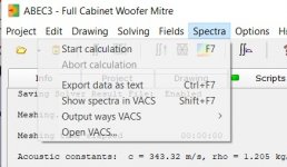
It seems I am not allowed to save the spectrum output from VACS, before plotting the 'noir' plots.
It seems I am not allowed to save the spectrum output from VACS, before plotting the 'noir' plots.
With the new report feature in Ath 4.7 you don't even need to run VACS (can be turned off completely), as the results are saved directly from the ABEC window (which saves quite a lot of time).
Last edited:
I don't know if it's the best way but this is how I would do it:
1) Use this undocumented (yet) feature of Ath, which creates an *.afp file:
2) Import the *.afp file into Autodesk Fusion 360 with the attached Add-In.Code:FusionRotaryProfile = { Thickness = 4 ; [mm] Flange.Radius = 50 ; [mm] Flange.Length = 8 ; [mm] Joint.Length = 0.35 Joint.Radius = 0.6 }
3) Make it solid by revolving it around the X axis and cut the holes...
4) Export as STL and print.
This all takes no more than about 2 minutes (not the printing part 🙂).
Wow Marcel this ATH Import is awesome, super easy to do. Thank You

Attachments
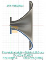
I'm stuck on the size for now.
My printer is limited, this the max size my printer can hold diagonally.
My printer is limited, this the max size my printer can hold diagonally.
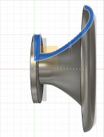
When you design a horn for a specific driver as in this case, I think you should model its exit section as well. You already did it:
Throat.Ext.Length = 65 ; [mm]
Throat.Ext.Angle = 3.6 ; [deg]
- The directivity is maybe not as well controlled as I would like (may be too narrow for that size) but why not to try that. Otherwise it's fairly smooth. Printing is cheap...
I think you made a pretty good job for the start.
Throat.Ext.Length = 65 ; [mm]
Throat.Ext.Angle = 3.6 ; [deg]
- The directivity is maybe not as well controlled as I would like (may be too narrow for that size) but why not to try that. Otherwise it's fairly smooth. Printing is cheap...
I think you made a pretty good job for the start.
Last edited:
Pretty good, thanks to you and your great ATH software.
I'll experiment some more before printing this weekend.
What's a good area to adjust that makes the most difference for a more controlled directivity with the size remaining constant? If possible...
I'll experiment some more before printing this weekend.
What's a good area to adjust that makes the most difference for a more controlled directivity with the size remaining constant? If possible...
With the new report feature in Ath 4.7 you don't even need to run VACS (can be turned off completely), as the results are saved directly from the ABEC window (which saves quite a lot of time).
restarting did something at least
Attachments
Nice [emoji106] I'll print it and now learn how to measure. This has been a fun and rewarding experience. ThanksI meant it was good. 🙂
Did you calculate the Spectra and export it as text?restarting did something at least
Attachments
Yeah, I just ran one of the demo projects without checking the content.
I just ran the .cfg that JSS uploaded, it worked fine
Thanks for the support
I just ran the .cfg that JSS uploaded, it worked fine
Thanks for the support
That is a massive time saver thanks 🙂1) Use this undocumented (yet) feature of Ath, which creates an *.afp file:
When you design a horn for a specific driver as in this case, I think you should model its exit section as well. You already did it:
Throat.Ext.Length = 65 ; [mm]
Throat.Ext.Angle = 3.6 ; [deg]
I think you made a pretty good job for the start.
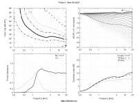
I ran it again with the Throat.Ext settings. The throat impedance skyrockted up.
Attachments
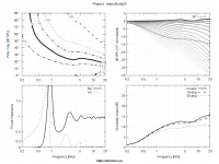
This is something I can't really explain and am still a bit puzzled that the effect is so strong even in such a relatively smooth case (if the simulation is correct), but that may be due to the long exit section. It seems that this happens when two different geometries (expansion rates if you will) are connected together, which causes a reflection at the interface. Here it is the conical section and the OS-SE throat. Earl Geddes already commented on that here (#2391):
Now it would be great to have this measued to see if it's real to that extent. If it was, the whole system would "ring", i.e. there would be strong peak(s) in the frequency response and accompanying ringing in the time domain. Correctable with EQ but somewhat troublesome. What's interesting is that it has virtually no effect on radiation pattern.
gedlee said:I had always expected a reflection at a aperture where, even though the wall slopes are the same, the actual wavefronts are not - the coordinate systems are not the same at short distances, i.e. the throat. Hence, a reflection and wavy impedances.
This is why I switched from the DE250 to the DE500 - shorter throat extension.
Now it would be great to have this measued to see if it's real to that extent. If it was, the whole system would "ring", i.e. there would be strong peak(s) in the frequency response and accompanying ringing in the time domain. Correctable with EQ but somewhat troublesome. What's interesting is that it has virtually no effect on radiation pattern.
Last edited:
That makes a lot of sense.
If you look at commercial compression drivers, they're getting shallower and shallower and shallower.
Some of that is marketing, of course: if you can make everything shallower you can stick waveguides into in-wall speakers and the like.
But it stands to reason that some of it is because it sounds better.
- Home
- Loudspeakers
- Multi-Way
- Acoustic Horn Design – The Easy Way (Ath4)