mabat, in the instructions there is mention of simulating a freestanding guide as an exterior subdomain only without an interface. Have you been able to do this successfully? I have tried with Ath and my own meshes and just generated garbage.
To get good results I needed to have the interface be on the last slice and offset enough to not interfere.
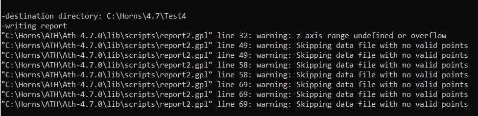
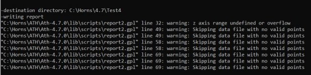
I have been trying to get the report function to work on a meshed xy freestanding horn but I get these errors. The vacs output looks OK, any idea what is going wrong?
To get good results I needed to have the interface be on the last slice and offset enough to not interfere.
I have been trying to get the report function to work on a meshed xy freestanding horn but I get these errors. The vacs output looks OK, any idea what is going wrong?
Attachments
I use it almost exclusively with the CircSym mode now. It's hard to say what's the problem without seeing the model. The report feature needs the right header captions to recognize the data - maybe that's why something is missing.
Last edited:
This is the config
This is the observation script
Code:
; Ath version 4.7.0
ABEC.MeshFrequency = 1000
ABEC.NumFrequencies = 48
ABEC.Polars:SPL = {
  MapAngleRange = 0,180,37
  NormAngle = 10    ; [deg]
  Distance = 3      ; [m]
}
ABEC.SimType = 2
ABEC.f1 = 600
ABEC.f2 = 10000
Coverage.Angle = 40
Length = 160
Mesh.AngularSegments = 64
Mesh.InterfaceDraw = 10
Mesh.InterfaceOffset = 30
Mesh.InterfaceResolution = 12.0
Mesh.LengthSegments = 20
Mesh.RearResolution = 10.0
Mesh.RearShape = 1
Mesh.SubdomainSlices = 19
Mesh.ThroatResolution = 5.0
Mesh.WallThickness = 5.0
Output.ABECProject = 1
Output.STL = 1
Output.SubDir = 4.7
Report = {
 PolarData = "SPL"
 NormAngle = 10
 MaxAngle = 90
 Width = 1024
 Height = 768
}
This is the observation script
Code:
Driving_Values
  DrvType=Acceleration; Value=1.0
  401  DrvGroup=1001  Weight=1.00 Delay=0.0

Radiation_Impedance
  BodeType=Complex; Range_min=0; Range_max=2; RadImpType=Normalized
  402   1001 1001   ID=8001

BE_Spectrum
  PlotType=Polar; GraphHeader="PolarMap_SPL"
  BodeType=LeveldB; Range_max=5; Range_min=-45
  PolarRange=0,180,37
  Distance=3m; BasePlane=zx
  NormalizingAngle=10
  501  Inclination=0  ID=5001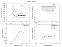
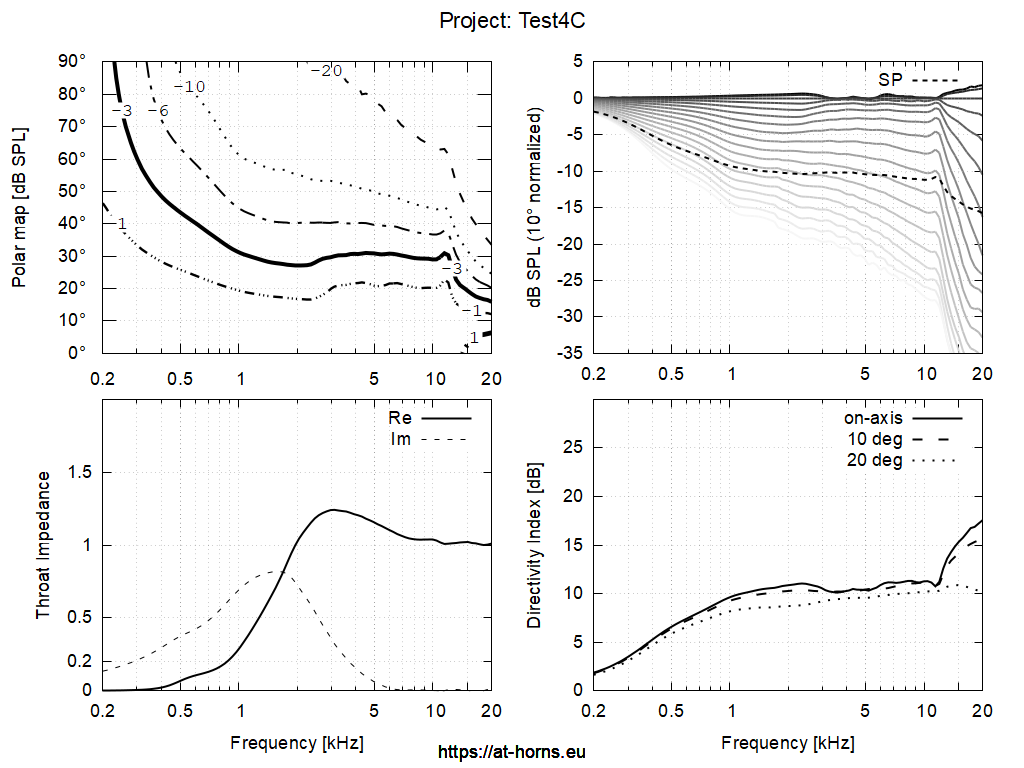
Do you mean you have the same waveguide shape calculated both with full-3D BEM and via the CircSym mode? I tried this and the differences were quite subtle.Not as clean as the circsym result, but still...
I would think that the ripples in the above report are more due to the waveguide itself.
Yes the graph above is the same guide, (a different set of frequencies 600 to 10K to reduce time when fully meshed) but otherwise no difference.
I had to reduce the mesh density more than usual to get the elements reasonable, and the interface made more of a difference this time. Where did you place the interface when the sims were similar?
The spiky ripple is definitely the sim rather than the guide.
Circysm test for comparison
I had to reduce the mesh density more than usual to get the elements reasonable, and the interface made more of a difference this time. Where did you place the interface when the sims were similar?
The spiky ripple is definitely the sim rather than the guide.
Circysm test for comparison
Attachments
Then I suspect something must be different between the two models. This doesn't look like a typical numeric issue (only).
IIRC, I placed the interface at the apex of the mouth (in the full-3D case) but don't remeber the details. But I agree that these details have weird effects sometimes. With the CircSym, I settled on using just one (exterior) subdomain.
IIRC, I placed the interface at the apex of the mouth (in the full-3D case) but don't remeber the details. But I agree that these details have weird effects sometimes. With the CircSym, I settled on using just one (exterior) subdomain.
Last edited:
hi
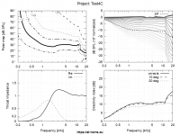
here is couple of my tries, one OS-SE for 1" and two CircArc, 1" and 1.4". All for asymmetric free standing WG's. They are looking promising, I hope so.
There is one thing what is not clear for me. OSSE show significant rise in DI when wavelength become smaller than throat diameter. On other side CircArc is almost flat. Is that some simulation error or inherent feature of CircArc design. If is it later is there any explanation for it
Attachments


You are definitely on the right track 🙂
The CircArc examples would be exceptionally good, IF you used a practicable source at the thoat - I suspect that you left the default, matching spherical source there (i.e. a pulsating one). Then it surely would be this good but such source doesn't really exist - no available compression driver will do that at the moment, I'm afraid (and maybe we still could try to make a one).
- Try to connect a common throat extension of a compression driver to the above models (Throat.Ext), driven by a flat wavefront (Source.Shape) and see what you get. Or just a flat wavefront directly, without any extension.
Last edited:
Yes, I left the default. Is it the option 2- flat wavefront more realistic?
Or I should model the source and implement it in script file. Easy to say but without CD almost impossible.
Are you modeling your horns with some source model?
What is your opinion about lack of DI rising in CircArc?
Or I should model the source and implement it in script file. Easy to say but without CD almost impossible.
Are you modeling your horns with some source model?
What is your opinion about lack of DI rising in CircArc?
I would use either flat or a spherical wave but with much larger radius (and in that case it's maybe best to try to simulate an exit section of a specific driver).
As I said, I find it realistic with that source. That's the reason I tried to develop the spherical wavefront phase plug - it could be this good, no matter the throat size, at least in principle. (In the end it probably woudn't because of other reasons.)What is your opinion about lack of DI rising in CircArc?
Last edited:
thanks for quick answer
by "much larger radius" did you mean "Source.Radius =" definition and if you did what is much larger, x1.5, x2.0 or even bigger
I hope I do not ask to much
by "much larger radius" did you mean "Source.Radius =" definition and if you did what is much larger, x1.5, x2.0 or even bigger
I hope I do not ask to much
I'm just guessing here because I don't know the wavefront shapes at the exits of compression drivers, but if there's a conical extension (as almost always is, although there are drivers without it), I assume a spherical wave corresponding to that exit angle could be used as the first approximation. Or just a flat wavefront..
Last edited:
in that case, isn't the best, what we have now, to define throat angle same as CD exit angle.
Try spherical and flat wavefront and take the worse.
Try spherical and flat wavefront and take the worse.
Last edited:
Sure. I was talking about what if you wanted to see how would your previously modeled devices behave when connected to a more common source, like a real-world compression driver.
Today I finally ordered 12 pcs of the smaller one (sand printed & epoxy impregnated) - ATH - Advanced Transition Horns 
one more question (not last for sure)
what exactly the "CircArc.TermAngle = " define? I've tried several values and did not notice any change nor in shape neither in results
what exactly the "CircArc.TermAngle = " define? I've tried several values and did not notice any change nor in shape neither in results
- Home
- Loudspeakers
- Multi-Way
- Acoustic Horn Design – The Easy Way (Ath4)