Mabat, as I understand it, all these simulations are performed in infinite baffle ? Did you try modeling the same horns as freestanding ? I wonder how much changes acoustic loading and directivity of your horns under different mouth terminations.
That's correct. Simulating it free-standing is a long awaiting addition. I already know how to do it, it's quite easy after all, I just have to sit down and write the code which is harder nad harder these days... The good thing is that when put into an enclosure, the results from infinite baffle are not that different - many of the horns presented are actually meant to be put into a baffle.
I agree that infinite baffle termination should be quite reasonable for boxed horns. I ask about influence of freestanding termination, because I fought for quite some long time with my horn for coaxial spekaer project that required freestanding termination. It was quite tedious task to find the optimal horn for such design. Therefore, your design looks quite interesting. Anyway, thaks for posting the simulation results, I understand well how long it takes. 
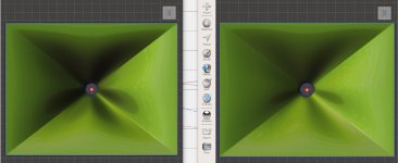
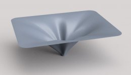
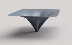
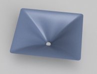
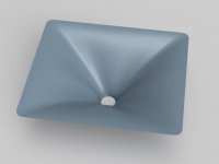
I have made a comparison of a deep and shallow version of my current best attempt at a rectangular guide trying to keep the outer dimensions as close as possible (400mm x 308mm). So not quite what you asked for but as the ABEC sims are already done maybe it is useful.Now I wonder what the radiation impedance of the same waveguide with a bigger mouth would look like, but I don't want to burden mabat with yet another time consuming sim.
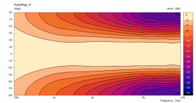
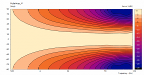
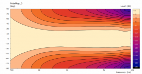
Image below side by side Deeper one (200mm) on the left shallower one (110mm) on the right.
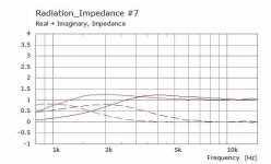
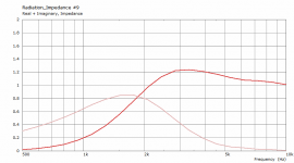
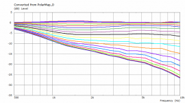
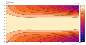
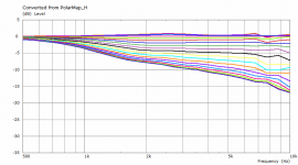
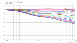
And the radiation impedance. Red Deep blue shallow.
Attachments
mabat, don't rush yourself.
Having said that, evidently I'm also looking forward to sims of freestanding ATH4s.
fluid, thanks for posting these sims!
As for the ripple, it seems that there is very little difference between the horns.
The short horn seems to exhibit even marginally more pronounced ripple.
Anyway, as far as I'm concerned, there's no sensible explanation.
Last edited:


One thing I didn't stress explicitly - these simulations are still calculated for a constant acceleration of the driving elements, there's no electroacoustical model of any driver connected. This is a different situation to a compression driver being driven with a constant voltage. Maybe this would be the right moment for incorporating such a model as ABEC allows for that. I just never tried and would need some help here.
I would love to see that. I'm working with hifi tweeters so nowhere near the hypothetical planar wavefront CD's are *supposed* to have.
This lumped element model, coupled to what I already have, should allow to predict real SPL for a given voltage and also the corresponding excursion. I'd be most interested in these quantities.
Last edited:
This lumped element model, coupled to what I already have, should allow to predict real SPL for a given voltage and also the corresponding excursion. I'd be most interested in these quantities.
What quantities are that? I have a compression driver model that I have fit parameters to, it's not too hard, just a few measurements of the electrical impedance and some known quantities does the trick. Generally manufacturers don't provide enough info.
I meant that I would be interested in sensitivity and excursion as the results of the simulation. As for the model itself, I have to explore the possibilities yet. I heve never done this so there is still so much to learn for me...
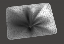
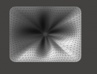
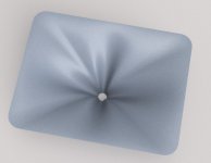
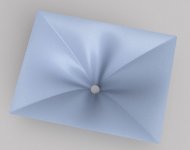
There was a request for a bigger version of one of my better designs. Here it is, 484 x 418 x 155 mm.
(It begins to be boring I guess... 🙂 )
To satisfy Ro808's urge for classification, I would call this type of shape T-Horn (as Tritonia is the name of the speakers for which this waveguide was originally designed). I call it horn although it is a pretty good waveguide as well...
(It begins to be boring I guess... 🙂 )
To satisfy Ro808's urge for classification, I would call this type of shape T-Horn (as Tritonia is the name of the speakers for which this waveguide was originally designed). I call it horn although it is a pretty good waveguide as well...
Attachments

Last edited:

fluid, thanks for posting these sims!
As for the ripple, it seems that there is very little difference between the horns.
The short horn seems to exhibit even marginally more pronounced ripple.
Anyway, as far as I'm concerned, there's no sensible explanation.
You're welcome 🙂
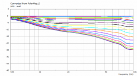
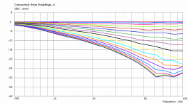
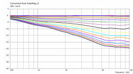
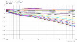
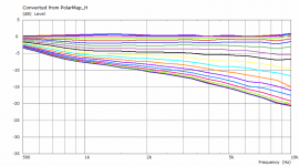
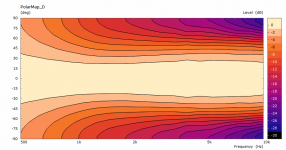
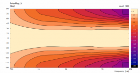
Any ripple or changes in shape shown in the Radiation Impedance can be traced back to the polar curves.
For example in the red graph there are a couple of bumps between 4.5 and 6.5 K, these can be seen in the polar curves.
The Blue curve has a rise at the top, the shorter version has a rise in output across all curves so the cause for that appearing is clear.
The smoother the polar curves the smoother the Radiation Impedance is. So in that sense the reason for the ripples in the graph is clear. Whether they will appear in reality is another question. I am not so sure that they are just sim artefacts that can be completely ignored if you are aiming to make the best waveguide possible through simulation. Having said that finding a way to get rid of them without making everything else worse is very difficult and as mabat said totally unintuitive. Most of my good results came more by accident that intention 🙄 But working with these simulations is giving me a better idea of what is working and what is not. I haven't got to why though.
I have tried a finer mesh and more frequencies on one simulation to see if that helped. It only made things look worse, not better.
What seems more important to me is how smooth these are in general, in the paragraph you linked before, finite exponential and conical horns showed quite considerable ripple. The ones from Ath look much more like the infinite exponential shown which I think is a real positive.
Attachments

fluid, thanks for the lucid explanation. There's very little to add.
Tedious Excellence?
How about the same mouth (484 x 418) x 198 mm + 1.4" ?
There was a request for a bigger version of one of my better designs. Here it is, 484 x 418 x 155 mm.
(It begins to be boring I guess... 🙂 )
Tedious Excellence?
How about the same mouth (484 x 418) x 198 mm + 1.4" ?
- Home
- Loudspeakers
- Multi-Way
- Acoustic Horn Design – The Easy Way (Ath4)