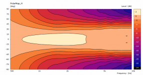
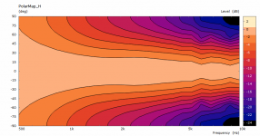
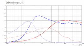
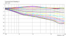
Gentlemen, you have to be slower with me, I'm just a monkey playing with a BEM simulation. What's so remarkable about it? The blue one is definitely a beaming device in my book.
One thing I didn't stress explicitly - these simulations are still calculated for a constant acceleration of the driving elements, there's no electroacoustical model of any driver connected. This is a different situation to a compression driver being driven with a constant voltage. Maybe this would be the right moment for incorporating such a model as ABEC allows for that. I just never tried and would need some help here.
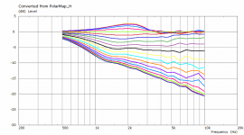
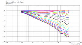
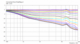
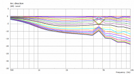
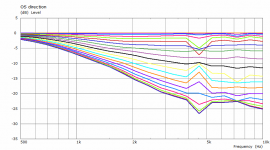
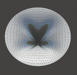
In a bit higher resolution, up to 10k -
One thing I didn't stress explicitly - these simulations are still calculated for a constant acceleration of the driving elements, there's no electroacoustical model of any driver connected. This is a different situation to a compression driver being driven with a constant voltage. Maybe this would be the right moment for incorporating such a model as ABEC allows for that. I just never tried and would need some help here.
In a bit higher resolution, up to 10k -
Attachments
...The blue one... up to 10k -
Thank you, the extended frequency does allow to see the expected trend to beam more for the superelliptical compared to the OS.
Still pretty impressive results.
Best wishes
David
Just to confirm, the horn in post #2206 with 1.4" throat is 447 x 290 depth, same as previous post #2205?
Last edited:
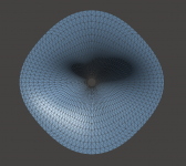
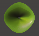
Now I'm waiting for this one 🙂 It is a blend of the two previous, horizontally the OS and vertically the arc. Easy to do with the tools I have now.
Yes, as far as I remember I changed just the throat diameter.Just to confirm, the horn in post #2206 with 1.4" throat is 447 x 290 depth, same as previous post #2205?
Attachments
Last edited:
...for this one 🙂 It is a blend of the two previous, horizontally the OS and vertically the arc. Easy to do with the tools I have now.
I look forward to it too😉
It seems to me that for a corner installation, as I have, that the boundary conditions are different for the horizontal (constrained by the walls very close) compared to the vertical (I have a tall "cathedral" roof).
So I expect the optimum horn to have a different profile horizontally and vertically.
So very interested in your results.
Best wishes
David

I already have the book but thank you for the consideration.
However, the quote I wanted to find was this one...
That quote is from Jack Oclee-Brown's PhD Thesis, page 49.
Last edited:
Gentlemen, you have to be slower with me, I'm just a monkey playing with a BEM simulation. What's so remarkable about it? The blue one is definitely a beaming device in my book.
Somehow I regret not mentioning the beaming that was to be expected 😎, as well as "the blue one could be a substitute for a Salmon type of horn".
Is there still something OS-like left in the throat of the blue one?
Last edited:
Well it's still a continuous function... 🙂Is there still something OS-like left in the throat of the blue one?
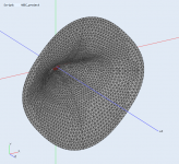
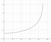
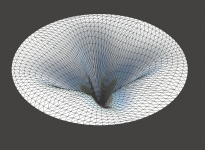
BTW, as the opening angle is decreased the OS doesn't look like OS as one might be used to when the angle is 90°. Would you call this an OS by looking at it? Yet it is, up to about x=60 mm pretty exactly...
Attachments
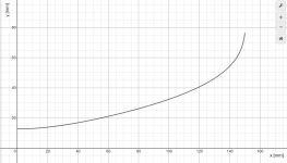
This is an OS up to about x=40 mm. But no, in the "arc" profile presented, there's not much of it anymore - at least not by design.
BTW, all these curves are still created with the same waveguide formula. I haven't been using anything else for a long time... Basically by this formula you can mix between a superelliptical arc and a straigh line (a cone), flared OS being somewhere between.
BTW, all these curves are still created with the same waveguide formula. I haven't been using anything else for a long time... Basically by this formula you can mix between a superelliptical arc and a straigh line (a cone), flared OS being somewhere between.
Attachments
Last edited:
Well it's still a continuous function... 🙂
BTW, as the opening angle is decreased the OS doesn't look like OS as one might be used to when the angle is 90°. Would you call this an OS by looking at it? Yet it is, up to about x=60 mm pretty exactly...
The low flare rate dominates the OS-throat, it seems.
Some time ago on this forum, I stated that an OS-throat is a kind of (soft) diffraction slot.
Either way, you can be proud of yourself, because ATH(W?)4s are among, and may be the best horns in the world.
Last edited:
It seems you really like classifications and their various relationships 🙂
I'm afraid my brain doesn't work like that so I really don't know what you are saying here 😱
I'm afraid my brain doesn't work like that so I really don't know what you are saying here 😱
Oh, you bet! 😀...ATH(W?)4s are among, and may be the best horns in the world.
Last edited:
Even more varieties would be possible if several layers of independently shaped segments were stacked on top of each other and smoothly joined (which would be easy in principle with the formula at hand)  Maybe to even better combine the loading and the directivity aspects.
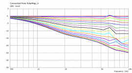
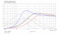
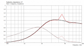
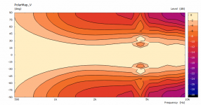
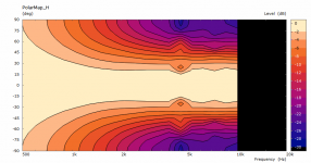
Maybe to even better combine the loading and the directivity aspects.The profile can swap twice as often around the waveguide (i.e. it is OS horizontally and vertically, arc diagonally). The impedance is still basically the same, which should be the expected result when I think about it....It is a blend of the two previous [profiles], horizontally the OS and vertically the arc.
(I don't know why but sometimes at some frequency the results are just completely off - you have to ignore the data here at 4.5 kHz.)
Attachments

so how many of these designs have been made into the real world devices? any sound files, evaluations, etc?
I don't know, a few. We are working on one right now.so how many of these designs have been made into the real world devices? any sound files, evaluations, etc?
- Home
- Loudspeakers
- Multi-Way
- Acoustic Horn Design – The Easy Way (Ath4)