BTW, I tried to implement an option of a simple radius for the mouth round-over but it's actually pretty awkward to calculate, much more difficult than the gradual termination - the math is so ugly that I will probably leave it unresolved 🙂
It seems that this was also the main reasoning behind the (tangerine) phase plug in the KEF coaxial drivers, as explained here: YouTube (time 9:14). I haven't thought about it that way before. Makes sense after all.... Why not to create the spherical wave as soon as possible?
Last edited:
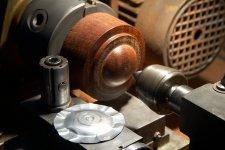
Otherwise the general task here is to connect the diaphragm "A" by a system of phase plug channels to the conical waveguide "B". At least in contrast to a concave dome this doesn't appear that impossible -
Attachments
Last edited:
Why not to create the spherical wave as soon as possible?
This is an advantage only if you know what the horn will be as different waveguides require different curvatures, etc. When making a driver for use with arbitrary horns, then a small circular flat wavefront is probably the best choice.
I did look for drivers that had the shortest phase plugs and found the DE500. It did work a little better, but it was not night-and-day better. Just a small improvement. So ideally what you suggest may have merit, but in practice it is not very practical and doesn't make all that much difference anyways.
I'm interested to see what will be the outcome as the sound from the center of the diaphragm will tend to have a much shorter route through the phase plug than that from the periphery.Otherwise the general task here is to connect the diaphragm "A" by a system of phase plug channels to the conical waveguide "B". At least in contrast to a concave dome this doesn't appear that impossible -
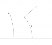
The drawing above was just to express what I meant in general. The paths should be made the same, of course. I don't see why they couldn't.
In fact, I still do think that the channels actually should be made shorter when getting closer to the center, due to the bending wave. The center gets pressurized a bit later than the rim because of the limited bending wave speed - we know the diaphragm is not rigid and it is the bending wave that excites the slots no matter what. I still feel that taking account of this, even if for a constant bending wave speed, should be better than nothing but it's really of out my scope at the moment.
I see I keep using the word "excites". Excitates is the proper one I guess 😀 Or is it the same in this context?
BTW, the Gmsh API is just fantastic for this - now the slots will be of cubic Bezier curves of the desired number and spacing, all of it parametrizable in the script file.
BTW, the Gmsh API is just fantastic for this - now the slots will be of cubic Bezier curves of the desired number and spacing, all of it parametrizable in the script file.
Attachments

Last edited:
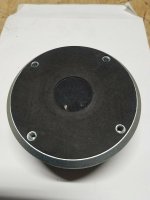
Celestion "deep-drawn" diaphragms might be well suited for the experiment -
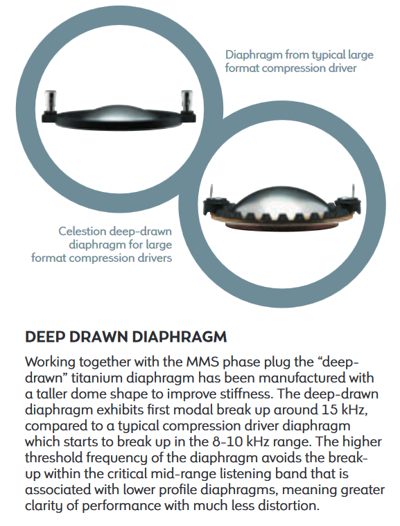
Stick to the CDX14-3030 and 3040 then, because the 3050 contains ferrofluid and is an earlier (new generation Celestion) driver, the break up of which "starts" way below 15kHz, despite its deep-drawn diaphragm.
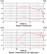
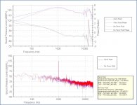
Someone ran a test with and without ferrofluid on a PWT.
Original Celestion plots attached for comparison.
Attachments
Last edited:
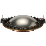
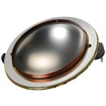
The diaphragm does look pretty cool though.
Normally you don't see this kind of phase plug in 3" (VC) drivers.
Normally you don't see this kind of phase plug in 3" (VC) drivers.
Attachments
Last edited:
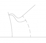
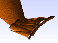
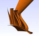
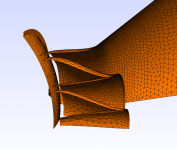
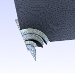
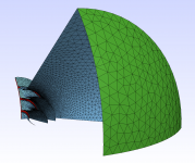
It slowly begins to look like a phasing plug -
(Don't judge on the geometry yet as this is just the very first verification of the generator, without any optimization.)
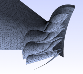
It works nicely. Some details still left to be solved.
(Don't judge on the geometry yet as this is just the very first verification of the generator, without any optimization.)
It works nicely. Some details still left to be solved.
Attachments
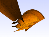
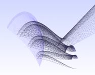
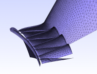
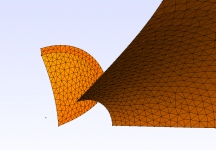
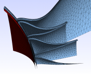
Or the center channel can be opened -
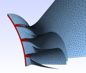
I really wonder how this will turn out. The starting and ending vectors of the channels (and the amount of "bending") can be adjusted freely per slot. This was automatically calculated for the volume velocities being in the same ratio as the projected areas of the entrances.
I really wonder how this will turn out. The starting and ending vectors of the channels (and the amount of "bending") can be adjusted freely per slot. This was automatically calculated for the volume velocities being in the same ratio as the projected areas of the entrances.
Attachments

- Home
- Loudspeakers
- Multi-Way
- Acoustic Horn Design – The Easy Way (Ath4)