Probably I missed something, but in what way is that different from testing compression drivers then?
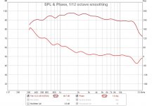
I understand that this might be hard to grasp and I may have said it wrong. The more the source deviates from flat the more HOMs there will be. HOMs decrease exponentially below cutoff and it is these evanescent waves that are so difficult to measure. Hence with a dome, one will have lots and lots of HOMs because the dome is not flat. This means that the measurements will be far less representative near the source than they would be for a flatter source. This error would propagate into any calculations of a waveguides effect, more or less depending on the waveguides specific design, rendering the results less than desirable. That's why I say that a measurement of a dome in a tube would be misleading.
Better would be a similar reconstruction technique where the dome is placed on an infinite baffle and its' radiation reconstructed from those measurements. But having tried this, the numerical instabilities are problematic.
Basically, by moving the crossover frequency lower (by means of a larger horn), the less of phase distortion there will be in the most sensitive hearing range - that's a simple fact.
As I understand it, any horn is a minimum phase device through the typical crossover region, so when equalized for a flat amplitude response, it would have a flat phase as well - there is no phase distortion from the horn itself. It is the all-pass behaviour of the crossover that distorts the summed time response.
Then wouldn't a larger waveguide end up being the same as a smaller one, if they were both EQ'd to be the same?
Now I understand, thank you.
It would, that's what I meant. The on-axis amplitude and phase responses would be the same. Or not?Then wouldn't a larger waveguide end up being the same as a smaller one, if they were both EQ'd to be the same?
There will be less phase distortion because of lower crossover frequency or because of a larger horn?
To self study how minimum phase looks for a given of a bandpass (its all pass behavour) suggest fire up free Rephase and use tab called "Minimum-Phase Filters", now set a HP and LP filter to form stop bands to kind of simulate acoustic slopes for a transducer and watch how phase turn 90 deg per order out of band and 45 deg in band, set for example some LR filters of a given order and see if you togle them between HP and LP their phase is same, tip do one filter then hit "Generate" button to freeze it as a red graph result and then shift filter be it HP or LP, also one can open Rephase multiple times and hover mouse over them multiple times of icons to simulate different setting of filters and how they compare.
To self study how minimum phase looks for a given of a bandpass
Thank you for the suggestion. Did you mean that unless horn+driver combination gives flat frequency response, the phase will grow towards the low frequencies?
Attachments
Thank you for the suggestion. Did you mean that unless horn+driver combination gives flat frequency response, the phase will grow towards the low frequencies?
As the lower frequencies roll off then the phase will increase.
To check for yourself in the control settings of the spl tab in REW press the generate minimum phase button which will give you a minimum phase version of the measurement and you can see if there is any excess phase there.
Thank you for the suggestion. Did you mean that unless horn+driver combination gives flat frequency response, the phase will grow towards the low frequencies?...
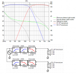
We can't hide minimum phase reality as fluid say thanks, phase follow amplitude as it vary up and down and especially exstreme at stopband because amplitude is not there anymore, be it a acoustic or electric case stuff is frequency dependant in high frequency is a shorter lenght in time than relative lower frequency so at a passbands HP corner phase will lag and at LP corner phase will advance. Your REW curve could get flat phase if it was EQed say flat amplitude down to 20Hz but voicecoil and stroke would get out of range, also never expect REW to show textbook phase in upper octave, that is because phase is at zero point at half of the used sampling rate so there is some visual distortion there compared to textbook visual in Rephase. As said maybe try some exercises in Rephase and maybe export as frd or wav and import into REW or use free VituixCAD as below example where you see a simple textbook 20Hz-20kHz system using 1kHz 4th order LR slopes, grey phase includes allpass summing reality and green phase was optimal for sum of system amplitude had one transducer could cover it all, difference between grey and green is also called excess phase.
Attachments
Last edited:
To me M2 style wavguide has very similar H,V,D directivity plot (60 deg coverage, 50cm length). Possible to draw it more rectangular in ATH 4.4.1?
I would have to check what changed in what release and probably get back to an older code which is something I hesitate to do. I remember I had to reduce the minimum for corner radius to 1 mm but don't know when.
Also the possibility of free-air (roundover) termination was removed in the last release, IIRC. It would be tiresome to modify it all in this old code - I won't do that. I didn't plan to touch it at all but as the writing of the new (redesigned) tool takes longer than I hoped for, at least I implemented the superformula which was easy. This is all I can offer for now.
Also the possibility of free-air (roundover) termination was removed in the last release, IIRC. It would be tiresome to modify it all in this old code - I won't do that. I didn't plan to touch it at all but as the writing of the new (redesigned) tool takes longer than I hoped for, at least I implemented the superformula which was easy. This is all I can offer for now.
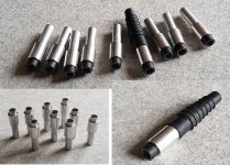
In the meantime I progress on the PWT hardware (mic plugs for 6 mm electrets) -
Attachments
Last edited:
gedlee
Re PWT, I'm not sure you mentioned this before - what about a (typical) conical exit of a compression driver connected directly to a straight duct? Wouldn't that deteriorate the results? I will have two tubes, ⌀1" and ⌀1.5" - would a smooth transition insert from 1" to 1.5" make sense for 1" drivers? These could be printed easily, I guess.
Re PWT, I'm not sure you mentioned this before - what about a (typical) conical exit of a compression driver connected directly to a straight duct? Wouldn't that deteriorate the results? I will have two tubes, ⌀1" and ⌀1.5" - would a smooth transition insert from 1" to 1.5" make sense for 1" drivers? These could be printed easily, I guess.
Last edited:
For anyone wanting to get any of Mabat's waveguides CNC cut I posted my method of getting the shape into Fusion 360 here. Thanks to limacon for pointing me in the right direction 😉
3D Modeling Tips and Tricks
3D Modeling Tips and Tricks
Have I missed something in that post or does that mold yield a part with no thickness (the front surface of the waveguide being the shape of the "rear mold").. unless it's a mold for casting the male mold part in..
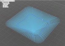
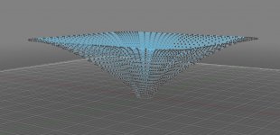
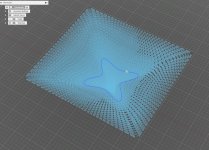
I have created a parametric model in Autodesk Inventor. Inventor has a pretty good equation curve feature (although it lacks a sgn-function when using polar coordinate equations like the superformula for instans). There is a mold making feature, which creates the mold parts based on the master drawn. One could easily input the mesh in such a model, automatize the thicken/solid process and use the mesh dimension a a driving parameter for the rest of the baffle.
I have created a parametric model in Autodesk Inventor. Inventor has a pretty good equation curve feature (although it lacks a sgn-function when using polar coordinate equations like the superformula for instans). There is a mold making feature, which creates the mold parts based on the master drawn. One could easily input the mesh in such a model, automatize the thicken/solid process and use the mesh dimension a a driving parameter for the rest of the baffle.
I did drop a line to Mabat but he seems to be busy. Whilst waiting for his reply, does anyone else have a full list of parameters one can use with this script? There's been few additions over different versions and would be nice to see all potential parameters listed in one message. Don't need any detailed explanation on each, just the name and value range would do nicely. Thank you in advance. 🙂
I shall update the user guide and consolidate the matter on the web but I'm occupied with other things. Sorry for this unrestrained way of doing it - I do my best 🙂
Last edited:
Appreciated boss. It's awesome stuff what you are doing and if you need a hand on manual, i'm happy to help. Although i understand that if i don't know the parameters, i can't really help that much. I shall remain waiting, no panic 🙂
I can easily export the surface coordinates in a text file that can be imported as spilnes in Fusion 360 (I already have a custom add-on for that). Would that be useful? Is it possible to create a smooth surface and then a solid body from that?
Attachments
Last edited:
So I will make this available. I hope someone would then present a procedure that everyone can reproduce - I'm not experienced in CAD modeling. That would be great. What about some "guide" curves for this loft feature? I can export various curves of the surface.
You can use centerlines to guide lofting, so they might be useful. I'm happy to experiment with this and report back. Drop me a PM and we can develop this together.
- Home
- Loudspeakers
- Multi-Way
- Acoustic Horn Design – The Easy Way (Ath4)