I still have six Panasonics WM-61 so I will start with those.The latest MEMS microphones have tiny ports, pretty decent specifications and cost only a few dollars each so well worth consideration.
You should also have a look into Makarskis PHD (Chpter 3):
http://publications.rwth-aachen.de/record/61507/files/Makarski_Michael.pdf
There are some measurements, they used a 1mm probe and also measured with a reasonable termination (a small horn/wg). They method they are using gives very good simulation results.
You could also try a more easy method, described here in Jörg Panzers Paper with AKABAK (the succesor to ABEC3):
http://pub.dega-akustik.de/ICA2019/data/articles/000394.pdf
But even without those advanced technics, when you use a modern type compression driver with very high to out of range break ups, with proper ABEC sims the results are already really good!
Best Regards
Andreas
Thanks, those are some comprehensive materials!

Yeah, I really don't expect making any real improvements. I'm just curious and also I desperately need to put my hands on something physical now - for too long I have been doing a purely abstract work.But even without those advanced technics, when you use a modern type compression driver with very high to out of range break ups, with proper ABEC sims the results are already really good!
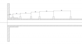
Would this be OK?... Just need to space the mic ports along the tube, probably in some random, certainly not equal, spacing. How many is up to you and your computational capacity.
(There are parts still missing in the drawing. This is only for the port spacing now.)
- Nah, now I see it's not very good. It's hard! I think I will really run a random generator and pick the one I like.
Attachments
Last edited:
Like 25, 36, 48, 61, 74, 88.
As to using gated measurements, I have always thought that should be possible, but honestly I don;t know anyone who has tried that.
As to using gated measurements, I have always thought that should be possible, but honestly I don;t know anyone who has tried that.
Questions, still -
1) What rotations (the angles) of the driver will be necessary?
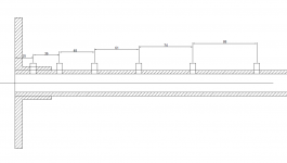
2) How critical is the first port distance from the tube beginning? I'm asking because if shifted more down the tube it would easily allow for a free rotation of the whole mounting flange without a need to re-mount the driver. Otherwise the rotation will be not so effortless.
3) Is the closer spacing at the beginning intentional, i.e. would it be worse if reversed?
1) What rotations (the angles) of the driver will be necessary?
2) How critical is the first port distance from the tube beginning? I'm asking because if shifted more down the tube it would easily allow for a free rotation of the whole mounting flange without a need to re-mount the driver. Otherwise the rotation will be not so effortless.
3) Is the closer spacing at the beginning intentional, i.e. would it be worse if reversed?
Attachments
There can be issues with close locations because of near-field effects (which can cause numerical instability,) so moving further back is not a problem. Rotating the driver on the mount can add data and find non-axisymmetric modes. I'm not sure if my math has that possibility, but it's not a difficult extension.
In PWT_modes.pdf you state "..., and the extension to a rotated driver is also quite straightforward.".
Well, it has been twenty years 🙂
OK, I'll move the ports a bit further. That will make it a lot easier.
Well, it has been twenty years 🙂
OK, I'll move the ports a bit further. That will make it a lot easier.
Last edited:
I thought that prof. Merhaut demonstrated that years ago but after I looked at his paper* again I see he in fact used short pulses as test signals (and then gated FFT). It was in 1985 so I wonder if it was because of the lack of todays techniques (MLSSA came in 1987, IIRC) or because it was so obvious to him that it would be wrong (but then I think he would mention that).As to using gated measurements, I have always thought that should be possible, but honestly I don;t know anyone who has tried that.
Is it really so different from making gated measurements of a speaker in a room?
* Impulse Measurement on Horn-Type Loudspeaker Drivers, Josef Merhaut (Vol. 34, pp. 245-254 [1986 April]); and more in Vol. 35, pp. 144-145
(Also in Loudspeakers anthology, Volume 4)
Last edited:
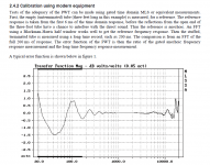
On the other hand, in the AES "Design and Practice" document, there is a calibration procedure using gated MLS presented as evident thing (see below).
We'll see. I have ordered all the parts for PWT, some custom CNC machined - two weeks delivery time.
Now back to horns 🙂
We'll see. I have ordered all the parts for PWT, some custom CNC machined - two weeks delivery time.
Now back to horns 🙂
Attachments
Last edited:
As I said, it should work, but I also have enough experience to know that we don't always know what we don't know, and "gotchas" happen all the time. To me only time tested repeatable results are to be taken seriously.
BTW, what about dome tweeters tested this way on a PWT? Would that measure their real wavefronts to any reasonable degree useful for further BEM simulation & optimization when used with horns?
In theory yes, but in practice - not without a lot of time and money. It would take a very high resolution of the evanescent waves which decay exponentially, so it gets very tough to measure these kinds of details. It would easily give you the shape that propagates down the tube. But waveguides act on the wavefront in different ways than a tube, so what you get in the tube is not what you can expect on a waveguide. You can easily do all these details numerically, but measuring them gets harder.
Possible but likely expensive.
Edit: In what I posted one would have to check if the functions change when the argument goes complex. Some algorithms can handle this others not. If they can handle it then it may just be a matter of more mics at ever closer distances. The problem is complicated and usually called "nearfield holography" but in this case it's quite a specialized situation.
Last edited:
Probably I missed something, but in what way is that different from testing compression drivers then?...But waveguides act on the wavefront in different ways than a tube, so what you get in the tube is not what you can expect on a waveguide.
I'd like to ask a quick question. Do making a larger horn make phase behavior more linear? For example, I currently use 30cm RCF horn and phase starts to grow below 1KHz. Will a larger horn of similar shape make the phase behaviour more linear?
I've not figured out how to use the software myself and asking for a quick opinion.
I've not figured out how to use the software myself and asking for a quick opinion.
Basically, by moving the crossover frequency lower (by means of a larger horn), the less of phase distortion there will be in the most sensitive hearing range - that's a simple fact.
Basically, by moving the crossover frequency lower (by means of a larger horn), the less of phase distortion there will be in the most sensitive hearing range - that's a simple fact.
There will be less phase distortion because of lower crossover frequency or because of a larger horn?
As I understand it, any horn is a minimum phase device through the typical crossover region, so when equalized for a flat amplitude response, it would have a flat phase as well - there is no phase distortion from the horn itself. It is the all-pass behaviour of the crossover that distorts the summed time response.
Larger horn will typically allow you to move the crossover frequency lower (provided the driver used is capable of it) - that's the benefit.
Larger horn will typically allow you to move the crossover frequency lower (provided the driver used is capable of it) - that's the benefit.
Last edited:
- Home
- Loudspeakers
- Multi-Way
- Acoustic Horn Design – The Easy Way (Ath4)