Unfortunately no minidsp products can run long enough filters to be useful. However Camilladsp on a rpi5 with dac8x runs multiple large .fir filters with no problem. (And Dac8x sounds much better that it has any right to!)
Ok, I'm fine with that. Because I assume you choose the crossovers based on the raw response measured.You measure each drivers raw response. Then set the crossover target accordingly (audiolense has some nice slow then fast rolloff filters). Then you set a room curve and the software calculates a .fir filter for each driver.
I'm also good with applying a room target curve on top the acoustic crossovers desired, to each driver's FIR filter.
I would call all of that setting up the speaker...so to me it just comes down to how did you take the measurements...
If it is at listening position, nope not for me.
If it is at quasi anechoic as possible, then yes for me.
After I get that done, I'll play with room correction under the assumption the best anechoic speaker I can make will hold up better spatially throughout the room, than one where the entire tuning and crossover decisions were built to a spot (even if the spot is matrix around listening position).
Btw, as to the length of FIR filters. There's no question in my mind anymore that for the quasi=anechoic tuning stage like I employ, less is more.
And that their length needs to vary per driver section.
Global room correction FIR length? dunno, but must admit I'm skeptical of longer filters....unless they are frequency dependent, reducing the time in play as frequency increases.
Observation distance is 3 meters. In practice, this just needs to be "far enough" relative to the size of the source.Forgive me for probably asking this again... what "mic" distance is the simulation done from and what "gate" is implied / used?
The simulation is free field, so no gate is needed.
Yes. The waveguide was completely omitted from that simulation. The reference point is unchanged (i.e. it's where the waveguide throat entrance would be if it were present) for consistency.To make sure we understood each other correctly: do I see the response only for the woofer in its second enclosure version (for the 'free-standing' waveguide), without the waveguide in place (neither firing nor reflecting)?
I haven't explored this, but it's certainly conceivable that a different crossover topology might be advantageous.asymmetric slopes and x-over points. Maybe this can counter the extra energy due to reflections without the need to cross as low as 550 Hz.
Yes, the BEM simulation only computes the directivity of each driver. In my case, I wrote a simple python script to apply the crossover and compute the system response from the BEM results. VituixCAD would be perfectly suitable for this as well.This lobe optimization is better suited for VCad work and extra simulation runs unnecessary.
It probably isn't realistic with this particular waveguide (standard 1 inch OS throat, so not so great loading at lower frequencies). Looks like it could perhaps be done with one of your "Gen2" devices though.550 Hz is not unreachable.
As a side note, I added a short (40mm) throat extension to my speakers some time ago (inspired by your experiments) and found that it reduced distortion considerably in the 1-2kHz range.
This is just a simulation with ideal constant-acceleration sources and unlimited "EQ" (normalization).Wait, sorry, how are you getting down to 550 Hz with the HF driver?
Finishing the 2" shaping plug adapter (here with A620G2)...


Is there already anyone interested/willing to participate in testing? This can be done with any existing Gen2 waveguide. I would send them the STLs.
Is there already anyone interested/willing to participate in testing? This can be done with any existing Gen2 waveguide. I would send them the STLs.
I've been playing with bempp_cl a bit over the last few days and found that the behavior you describe does appear to be related to the JIT compilation. I installed version 0.4.2 from PyPi usingI have started playing with bempp-cl which seems to the current version and it is not running efficiently for me.
pip. So far, I've only used the Numba backend. The first call to any JIT-compiled routine is slow (compilation appears to be single-threaded); subsequent calls are much faster and utilize all available cores.I decided to try uniform sampling rather than the typical H/V orbits and found that the H/V orbits actually seem to underestimate the true effect on the sound power for this as well as in-phase (LR) crossovers. This is the waveguide-in-baffle version again, computed with bempp:How does it look along a diagonal? Maybe the equal H/V weighting in the calculations is giving the vertical response too much weight.
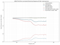
No NUC, unfortunately (I haven't figured out the requisite math yet). Now with the sound power computed from five thousand samples (a bit overkill, I know), approximately uniformly distributed[1] on a spherical surface:
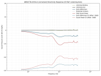
[1]: Using the "golden spiral" method.
That really needs to be tested, but I don't believe it will help in that case. I have my doubts even about the Axi2050, which should be about the best what seems available in this regard (maybe some of the ultra-expensive beryllium stuff could be better). Coaxes are in general known for having pretty ragged HF wavefronts.Will it work with BMS 4592ND coax? If the timing and wavefront is on spa.....
Last edited:
bmc0, your crossover is way too high frequency compared to size of the box, woofer and waveguide. If you wanna cross say at 1kHz, with smooth power and DI, you'd be better off with 8" or 10" woofer and waveguide. In general, for smooth transition use waveguide that is smaller or similar size as the woofer, roundover included, and box that is not much bigger than the woofer. Waveguide freestanding on top if you can. Crossover somewhere 1-1.4 c-c wavelength with LR filters. This makes sure woofer DI ramps up bit lower in frequency than waveguide DI, and enables smooth transition together with suitable xo frequency not to lose too much power off-axis in destructive interference. If you want to use very big waveguide use very big woofer, or multiple, and accordingly low crossover point.
If c-c is ~50cm, then use say ~50-70cm wavelength crosover, roughly 500-800Hz, for smooth transition.
I see your spins use waveguide as rotating = listening axis. With big c-c like this, you might want listening axis between waveguide and woofer instread, in order to keep distance to ear from each sound source relatively constant no matter listening distance. This has possibility to increase highs in the room as well, if thats good or bad thing, depending whats you DI on highs and room acoustics. This is something I haven't fully thought through yet though.
Last edited:
I disagree.bmc0, your crossover is way too high frequency compared to size of the box, woofer and waveguide.
The C-C spacing is 32cm and the crossover is LR6 acoustic at 1050Hz. Almost exactly one wavelength.Crossover somewhere 1-1.4 c-c wavelength with LR filters.
With an observation distance of 3 meters, it doesn't make much difference.I see your spins use waveguide as rotating = listening axis. With big c-c like this, you might want listening axis between waveguide and woofer instread
With the ~32cm c-c try ~32cm cubicle box, ~32cm diameter woofer and ~32cm freestanding waveguide, xo above 1kHz. You could very well use 26cm freestanding waveguide like good old st260 for example.
Last edited:
I've been playing with bempp_cl a bit over the last few days and found that the behavior you describe does appear to be related to the JIT compilation. I installed version 0.4.2 from PyPi usingpip. So far, I've only used the Numba backend. The first call to any JIT-compiled routine is slow (compilation appears to be single-threaded); subsequent calls are much faster and utilize all available cores.
Perhaps I ought to give it another go but I am struggling to see the purpose of the software. The initial intention appeared to be a BEM toolkit in a similar manner to the various FEM toolkits. A very worthwhile objective but a more challenging task than a FEM toolkit because of the additional need to address regularization, singularities, approximating full matrices with heirachies of some form, etc... But the toolkit part seems to have been largely dropped with the move to python. If I was a cynic I might suggest there seems to be a greater interest in fashionable computer languages (regardless of their appropriateness) than there is in the boundary element method.
ps, if somebody wants to experiment to find out what sized waveguide makes good response with some particular sized woofer and box one could simulate one size waveguide, and then just scale the data with a python script to get any size waveguide in few seconds.With the ~32cm c-c try ~32cm cubicle box, ~32cm diameter woofer and ~32cm freestanding waveguide, xo above 1kHz. You could very well use 26cm freestanding waveguide like good old st260 for example.
This is possible because when physical object size grows or shrinks, the acoustic features move lower or higher in frequency accordingly. Wavelength is basically physical size of sound so for example ideal 6" woofer response looks exactly the same as ideal 12" woofer response, except everything is just an octave higher in frequency. Same works for waveguides.
There would be error on the top and bottom octaves scaling it like this, but since the area of interest is on the mid band one can do it this way to get into ballpark very fast, then could do proper simulation to verify just in case.
One could scale a box and a woofer together as well, but it's enough to find good combination of any size woofer and scaling just the waveguide. When good size ratio is found then just apply that to any sized system. For example if you find out 32cm woofer and box works fine with 32cm waveguide and 32cm c-c, or what ever, then it would work just the same with 64cm woofer, 64cm waveguide and 64cm c-c, all the data on frequency plots would just move octave lower.
Of course we don't have 64m woofers available, so pick a woofer you want, like 8" and you get 20cm everything. +-10% on any of them doesn't make too big of a difference so there is some adjustability for aesthetics. There is no black magic in this, it's just sound interacting with physical objects.
Last edited:
The main issue that @bmc0 was showing is the effect of a waveguide on the response of the woofer. If the woofer remains fixed, the scaling obviously doesn't work any longer. There will be some (probably not that difficult) dependancy on the waveguide size, but not just a simple shifting in frequency, I guess.
Yeah thats one anomaly simple scaling of data doesn't work for. But, simple scaling would show that shrinking waveguide size works actually quite fine. Smaller waveguide helps also with that particular issue being smaller having less effect on long wavelengths in the woofer response. Additionally a freestanding version with quite big c-c and one edge between woofer and waveguide reduces the effect bit more, minimal symmetric baffle helps as well. It's not gonna fix all things, just an example that gives smoother response, get's rid of the particular kind of wiggle bmc0 illustrated.
Last edited:
If I remove the direct sound from in-room measurements of my speakers (via windowing) and look at only the indirect sound, I do indeed see a small dip around the crossover point along with a plateau in the 300-600Hz range. It depends somewhat on the particular location, but averaging a number of points on a horizontal plane seems to show this shape reliably.I'm sure many are scratching their heads right now, me included.
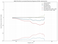
Here's the woofer from the above sim; first with H/V orbits and then with uniform sampling:
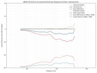
And the tweeter:
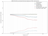
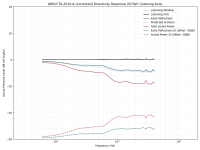
I don't quite understand @tmuikku's assertion of the crossover frequency being too high or the waveguide being too big. Ignoring the woofer anomaly caused by the waveguide, the DI of the woofer and tweeter are very similar over a wide frequency range. A smaller waveguide may well have less effect on the woofer though.
I've not used the old C++ version, but it also provided a python interface. As far as I know, the current incarnation is roughly equivalent in functionality to the old python interface, but perhaps not compared to using the C++ library directly. You're likely already aware, but the old code is still available here.Perhaps I ought to give it another go but I am struggling to see the purpose of the software. The initial intention appeared to be a BEM toolkit in a similar manner to the various FEM toolkits.
I've not used the old C++ version, but it also provided a python interface. As far as I know, the current incarnation is roughly equivalent in functionality to the old python interface, but perhaps not compared to using the C++ library directly. You're likely already aware, but the old code is still available here.
The C++ code seems to contain a range of finite elements which is kind of the point of a toolkit. The bempp-cl code has zero order and I think 1st order triangles. Not sure it even has quads. The functionality seems to be on par with a teaching code of a few hundred lines of C or Fortran. Perhaps the plan is to take a (large) step backward before moving forward developing/redeveloping a toolkit in rust given the number of separate rust repositories on github and the recent commits. Or perhaps the C++ toolkit was in such a state it needed dropping. Or perhaps... I don't know the story.
I think it may be wise to wait for the rust version to appear. Given Dmitrij_S has reported timings an order of magnitude quicker than I am seeing with my current installation I think it is safe to assume there is something wrong with the numba/opencl/... side of my bempp-cl setup.
There's a bit of discussion about that here.The C++ code seems to contain a range of finite elements which is kind of the point of a toolkit. The bempp-cl code has zero order and I think 1st order triangles.
- Home
- Loudspeakers
- Multi-Way
- Acoustic Horn Design – The Easy Way (Ath4)